Draw me the gyrator
Voilá.
BTW Ale' site http://www.bartola.co.uk/valves/ is good starting point to understand "gyrator"'s operation.
Attachments
E180F, E280F and 7788 should all be up to the task and are a little more obtainable these days.
Is "obtainable" the most important aspect in our hobby?
")
BTW I'm a collector of graphite anode 801.
I use both of these tubes, but in the right place.
D3a an E280F (as CCS loaded VAS) is interchangeable in my 300B amplifier, but have a little different character (I have several tubes of them, from several manufacturer).
D3a is the "rock", E280F is "sophisticated".
E180F/6688 is a little "weak" in this operating point, and E810F/7788 is a little "boring".
E810F is very good tube (for example in phono), but "hate" large swing, distortion (H3) is very quickly increasing.
As you can see in Pete Millett's site High Gm driver pentodes , among them the D3a is the most "better" (Gm, swing, THD) for using as two stage amplifier VAS stage.
E180F / 6688 is a little "weak" ...
Yes.
The E180F is a little preambitious tube. From data sheet the max dissipation is 4W (Pa + Pg2) ... that is too much for this little-glass tube.
In old broadcast repeaters, the E180F was the most "short of life" tube.
Btw, E180F is a great tube for us DIYers, but dissipation should not exceed 2W.
Thanks. The 300B went away to play music for someone elseHi mbrennawa...awesome website and writing!
Do you use the parallel 300B? Which pre-amp?
Really great...I'll be reading more!
E180F / 6688 is a little "weak" ...
Yes.
The E180F is a little preambitious tube. From data sheet the max dissipation is 4W (Pa + Pg2) ... that is too much for this little-glass tube.
In old broadcast repeaters, the E180F was the most "short of life" tube.
Btw, E180F is a great tube for us DIYers, but dissipation should not exceed 2W.
Regarding the E180F, The Mullard datasheet notes the pa max. at 3 watts. That is obvious for a small envelope. I have had no problem running the Tesla gold pin ones at about 2.3 watts. I find 175V on the plate biased for 13mA to be pretty nice. mu is almost 50, just like on the datasheet. Also nice is that they are pretty consistent (unlike so many soviet valves). Ok, once in a while you do get a dud, but they are not that often, and for the price, I just can't slag this little guy. Short life? like 2'000 hrs... I wish china 2a3's would last that long.... Also, I find that it is one of the most forgiving of all the UHF pentodes when triode strapped. On super cheap builds, with garbage iron it simply shines...
But, unless you are a true hobbyist, please don't buy this tube. its crap. honest. It seriously sounds like total garbage. Ignore what I wrote above. It breaks if you drop it. It's made of glass. Don't touch it with a barge pole. it should be only sold in large lots on the cheap to foolish buyers (like me)
Last edited:
Member
Joined 2009
Paid Member
Is "obtainable" the most important aspect in our hobby?
BTW I'm a collector of graphite anode 801.
I use both of these tubes, but in the right place.
D3a an E280F (as CCS loaded VAS) is interchangeable in my 300B amplifier, but have a little different character (I have several tubes of them, from several manufacturer).
D3a is the "rock", E280F is "sophisticated".
E180F/6688 is a little "weak" in this operating point, and E810F/7788 is a little "boring".
E810F is very good tube (for example in phono), but "hate" large swing, distortion (H3) is very quickly increasing.
As you can see in Pete Millett's site High Gm driver pentodes , among them the D3a is the most "better" (Gm, swing, THD) for using as two stage amplifier VAS stage.
Maybe its taste, but I prefer the E280F to the D3a when driving 2a3 or 45. The E180F does surprisingly decent job as well though. It is true that the E810F needs some care in implementation.
Last edited:
Maybe try 6E5P, when triode wired it's superbly linear and one of the favourites of our Russian DIY hobbyists.
I heard it a while back at a friend's, and it is indeed impressive! Nice price too, but make sure to buy a bunch to find a pair that have a similar gm.
Hi, there are some nice IXYS depletion mosfets that can be deployed as CCS cathode biasing,PartDetail
faithintruth,
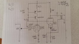
1. Your schematic in post # 14 still has the current source transistor Emitter connected to the input tube plate. That is incorrect for a PNP transistor.
See the schematic in post #20 for the correct connection of the PNP transistor Collector to the input tube plate.
2. For all of you who know one input tube sounds better than others, there is an interesting aspect that changes the sound of the amp:
A. The second harmonic of the input tube is in opposite phase of the second harmonic of the output tube.
B. Depending on how close the percent of second harmonic distortion matches, the amount of second harmonic distortion can cancel to a greater or lesser degree.
C. But it is not all that simple, because the settings of quiescent voltage and quiescent current of both the input tube, and of the output tube determines the amount of second harmonic distortion in each one. That can change the match of the percent distortion that cancels more of less according to how close that match is.
D. Another factor that changes the second harmonic distortion of the output tube is the load. Different loudspeakers present different average loads, and the load of a particular speaker changes versus the frequency.
In all listening comparison tests of input tubes, your mileage may vary, depending on B. through D. above.
Any thoughts on this (Thomas Mayer) power supply for my amp
(Medwin LCLC + Mayer 6AX4)
This supply using the 5AR4 was drawn by a friend. There is always the original supply by Tucker (?)
30µF is low for supply. impedance at bass freq is too high.
even my stax amp with lowish current got big sound improvement with 12H+1000µF
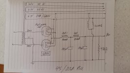
Any help with values would be cool.
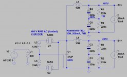
350V AC is too low, especially if you want to use choke input (LCLC) filtering (probable 250-280V DC output -at 100mA load, with lowest DCR chokes-).
Try this configuration.
Attachments
Any help with values would be cool.
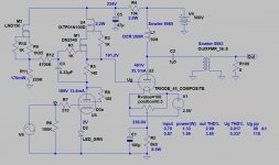
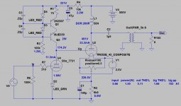
IMHO, the amp's schematic is good (if you want to use C4S....for me cascode CCS is better), but 4k4 cathode resistor value is wrong.
See 45's datasheet, if you want maximize power output, the targeted operating point is:
- maximum 275V anode-cathode voltage;
- 34...36mA;
- about 50...56V bias.
The first stage's (D3a) anode voltage is about 170..175V (anode current is about 10-11mA).
175V+56V= 231V
231V/36mA= 6417 Ohm
B+ is about 231V+275V+(36mA*OPT_DCR), for example 231+275+7= 513V
Target: 500V.
Sample schematic attached.
Attachments
Any help with values would be cool. I tried to digest "Testing power supplies"....
Ok, looking at the 45 curves I'd try biasing the 45 at 250V (anode-to-cathode) and 35 mA or so. That's a grid-to-cathode voltage of -50 V. The 35 mA bias current through the 45 gives 154 V across your 4.4 kΩ cathode resistor. So about 155 V at the cathode. Assuming a 1 kΩ DC resistance of the 50 H choke load, there's 35 V across the choke.
Adding up the voltages across the cathode resistor (155 V), the tube (250 V anode-to-cathode), and the choke (35 V), you end up at a B+ about 440 V. Your 300-ish B+ voltage would be too low for your 45 set up with a 4.4 kΩ cathode resistor.
But do you really need this value of cathode resistor? You can look at this resistor as a way to move the grid potential of the 45 up/down relative to the plate of the D3a. You need to adjust this such that the 45 cathode is 50V higher than the 45 grid, and hence the D3a plate. In other words, the cathode resistor value needs to jive with the biasing of the D3a.
I tried to figure our your biasing point of the D3a, but was not sure about the LED bias. The voltage drop of the two HLMP-6000 LED is about 2 x 1.6V, so you'd have the D3a biased at a -3.2 V grid voltage. Looking at the D3a triode curves, that seems a bit too much!?
Where / how do you want the D3a biased?
Last edited:
Member
Joined 2009
Paid Member
I heard it a while back at a friend's, and it is indeed impressive! Nice price too, but make sure to buy a bunch to find a pair that have a similar gm.
The benefit from triode-wiring it is to greatly reduce the impact of gm variations because for a Triode the gain depends on mu and we see that for most triodes the mu varies much less than the gm.
I tried to figure our your biasing point of the D3a, but was not sure about the LED bias. The voltage drop of the two HLMP-6000 LED is about 2 x 1.6V, so you'd have the D3a biased at a -3.2 V grid voltage. Looking at the D3a triode curves, that seems a bit too much!?
Where / how do you want the D3a biased?
If you want to use LED bias, don't forget the possibility to use IR LED's. I have used ones with as little as 1.2v forward voltage in some topologies with E280F or D3a. I have also used green LED's before as euro21 suggests. They can work well too.
Ian
Last edited:
Hi Ian - I'm unfamiliar with the D3A. I'm not committed to it and chose it after a friend suggested it's use. The original design of this circuit called for a medium mu twin triode 5965. As for biasing I have never used LED's.
euro21....wow....getting warmer I think.Thanks for running the numbers. I will continue to study the latest schematic. 6.8k is better on the 45. Do you like the MJE350 better? For 45 aimimg for 34mA-36mA for sure. No clue about which plate load choke to get. The Magnequest is $$$
euro21..Which program are you using...will it re-calculate on the fly? 5.1%THD at full output? Is this a pretty expected amount?
- Home
- Amplifiers
- Tubes / Valves
- 45 amp build direct coupled