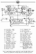
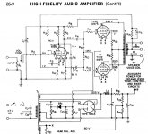
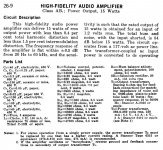
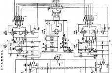
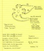
Hello Everyone, I need some advice please. I have a Knight Kit Stereo 40, KA-55 Amplifier that is trashed. I want to use the Power and Output transformers for this project if feasible. The first RCA schematic comes up in a few places on line. The second schematic also shows up on the net and has a few voltages attached that some seem incorrect in the power supply. Also attached is an ultra linear set up from a Seeburg jukebox amp that uses the same value resistors for the 7199 tube as the rca schematic shows. What I want to do is use 6GH8 and 6CZ5 tubes in this amp and use it as a power amp. I started working on a schematic according to the Sylvania 6CZ5 tube data sheets and what I have on hand around here. Please be kind, this is my first project and I am stumped as to if this will even work. I have rebuilt several amps in the past. Thanks, Tom
Attachments
Last edited:
If possible, please provide the original Knight schematic.
A 100 Kohm log. taper part will be fine as R1. Perhaps the uploaded schematic fragment will help in sizing R8. Assume parasitic oscillation will be present and suppress that nasty with carbon composition stopper resistors on all control grids.
As it is unlikely your 6ZC5s are well matched, "stand" each O/P tube's cathode on a 1% tolerance 10 Ω resistor and employ individual bias trim pots., to match "idle" currents. Measure the voltage drop across the 10 Ω part and apply Ohm's Law to calculate the "idle" current.
Do you have any gas discharge regulator tubes on hand? Full pentode mode O/P tubes yield max. open loop linearity, when g2 B+ is regulated at a fraction of anode B+.
Attachments
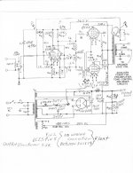
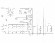
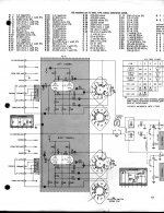
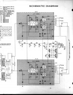
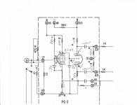
Thanks Ed, Attached is part of the KA-55 schematic and the power supply schematic. I do not have the instructions for the kit. I do have around 20-30 tall bottle RCA nos 6CZ5 tubes and some Sylvania's also. I should be able to find a matched quad. I do not have any gas discharge regulator tubes.
Attachments
I can do the carbon composition stopper resistors on all control grids and put the output tube cathodes on a 1% tolerance 10Ω resistor and employ individual bias trim pots to match the idle currents.
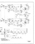
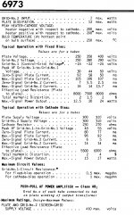
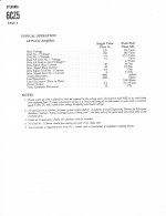
Attached are the 6973 and 6CZ5 tube specs for type AB amps.
Attached are the 6973 and 6CZ5 tube specs for type AB amps.
Attachments
Last edited:
Even with well matched tubes, separate bias trim pots. are a good idea.
You may be in trouble using a 5U4 rectifier, which draws 3 A. of filament current. The OEM 5AR4/GZ34 draws 2 A. Also, the forward drop in a 5U4 is greater than that in a 5AR4. You can completely dodge the vacuum rectifier issue by using 2X 1200 PIV Schottky diodes.
You are fortunate in being able to FWCT rectify the bias supply. A couple of these Schottky diodes will do nicely.
If I read the 6ZC5 datasheet correctly, stacking a 0A2 & a 0B2 will take care of regulating g2 B+. A stack in each channel will surely work.
If I read the 6ZC5 datasheet correctly, stacking a 0A2 & a 0B2 will take care of regulating g₂ B+. A stack in each channel will surely work.
BZX85B100-TAP Vishay Semiconductors | Mouser is I prefer, myself. But I freely admit not having affinities for the beautiful light show gas discharge tubes offer. I kind of like the 45¢ unit cost, and the fact that Zeners last essentially forever in service.
The only reason I didn't do a Mouser search for 220 or some other higher voltage is that I also like the added dissipation that stacked 45¢ Zeners offers.
_______
Since I completely respect your opinion(s) Eli, might it not also be reasonably good advice to float using series-with-cathode voltage regulator chips as "set-and-forget" constant-current references? Instead of 10 Ω current-sense resistors and potentiometers to adjust things?
We'd bypass them of course with both a nice mid-value electrolytic (220 μF at 33 VDC) and a polypropylene HF bypass (4.7 nF, 100 V). So the semiconductor auto-biasing scheme becomes acoustically “invisiblized”. Sorry about the made up word.
I agree with your assessment of vacuum rectification, and the utility of using hi-PIV Shockley diodes as alternate (and cheap, and good) rectification. It isn't clear to me why one wouldn't use the 45¢/ea parts for a full-wave bridge (4 diode) configuration, but hey… I trust your intuition.
Anyway, my 2¢
GoatGuy
A Dyna ST-70 board configured for 6GH8s is reasonable. However, the 7199 parts values from the SCA-35's power section could be best. Like the ST-35, the SCA-35 uses EL84 "finals"
Would kindly you link to the driver board under consideration.
The Sovtek 5AR4 will serve you well, provided you install the series SS diode tweak. I suggest you use UF4007s, instead of the 1N4007s shown, given the concept that less SS switching noise, from the outset, is better, even though the vacuum rectifier blocks the noise.
Attachments
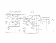
Thanks Eli, attached is a link to the 6gh8 driver board I want to use, also attached is a schematic of the PC-3 board with changes.
DYNACO ST-70 6GH8 6GH8A ECF82 Driver board PCB PC-3 KIT Dyna ST70 | eBay
DYNACO ST-70 6GH8 6GH8A ECF82 Driver board PCB PC-3 KIT Dyna ST70 | eBay
Attachments
Be prepared to "pad" the volume control with some additional resistance. The pentode voltage amplifier may do its job too well and yield more gain than is necessary. The symptom of this situation is barely moving the volume control from 0, before the sound is too loud. FWIW, this is called a "hair trigger" volume control.
BTW, the 470 Kohm resistor shown across the I/P is replaced by the volume control. The control's wiper connects to the voltage amplifier grid.
BTW, the 470 Kohm resistor shown across the I/P is replaced by the volume control. The control's wiper connects to the voltage amplifier grid.
I have an unbuilt Glassware Volume Attenuator A3 that should work nicely in that spot.
How about one of these automatic bias boards?
Automatic bias board.
Couldn't this solve some problems?
How about one of these automatic bias boards?
Automatic bias board.
Couldn't this solve some problems?
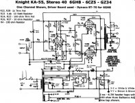
Adjust the value of the 820K screen resistor if needed to get 75-100V on the 6GH8 pentode plate. The 1K bias trim pot won't do anything unless you add a resistor to ground at the junction of R9 and R10 to make it a voltage divider (I'd reverse the two, few K fixed resistor from bias supply, 10K pot to ground). Bias at about 30 mA - also I'd bypass the 6CZ5 cathodes (or use separate bias pots to each one, delete the 100 Ohm cathode trim pots - 2 pots instead of 3). That's assuming there's enough bias voltage - minus 23V should be enough.
The cathode should be bypassed if they're used, will give a small amount of bias adjustment (3V or so), so you'll like likely need another bias adjustment. A pot in series as shown won't adjust anything, 1K is too low to use as a voltage divider - 10K would be about right. 1k would work, but there would be more ripple on the bias supply and it would be dissipating 1/2 W or so.
- Status
- This old topic is closed. If you want to reopen this topic, contact a moderator using the "Report Post" button.
- Home
- Amplifiers
- Tubes / Valves
- 6GH8-6CZ5 Tube Amp Project