Hi, Wavebourn,
I grounded the power supply directly at the rectifier. No hum or buzz. Any other point created a hum or buzz. In the attached photo, see the black wire originating from board just under the horizontal orange drop capacitors and going up and over to the chassis lug on the far right.
I grounded the power supply directly at the rectifier. No hum or buzz. Any other point created a hum or buzz. In the attached photo, see the black wire originating from board just under the horizontal orange drop capacitors and going up and over to the chassis lug on the far right.
Attachments
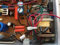
Power supply
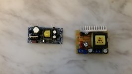
What are your thoughts on using a switching power supply. i have a ac-dc converter and a dc to dc booster. I can use these to get the B+ voltage to run the phono preamp. I was going to try this out and see how it works. If it works well I'd keep it if not i can build a tradition power supply. Eli do you have a better resolution image of that schematic for the power supply?
Greg
Attachments
Gregas,
Here is a pdf file of the power supply. I hope it will help.
You should draw the ground from electrolytic filter capacitors, instead of from the rectifier, to avoid pulses charging them to be applied to the signal. It may not be a problem in your particular design with very short trace between rectifier and the cap, but people following such schematics make the same error again and again.
What are your thoughts on using a switching power supply.
I'm not a fan of potential noise makers in audio circuitry. However, you can give it a whirl and observe what happens.
Have you given thought to a DC heater supply?
Sorry Wavebourn, schematics are explicitly NOT meant to convey wiring or layout information. Look it up in your favourite reference book if you don't believe me.
Why are you sorry?
My favorite reference book is a school book about electricity and Ohm law, with problems to solve about series and parallel connections of resistors, assuming that ground wires also have resistances, and currents that flow through them cause voltage drops.

Yes, schematics are schematical and do not have to show layouts, but it is a very common mistake when people treat them literally. Especially, when they insist that the layout as drawn on the schematic is the best, results in less hum and buzzing.
I get no profit from stressing common errors; contrary, I would benefit if my competitors make such mistakes routinely. So, why you should be sorry then?
Some of those AC to DC modules output 12 V DC, so that might be a possibility?Have you given thought to a DC heater supply?
Jeff
Thanks for the better resolution image.
Eli and VictoriaGuy
I will give it a go. I have a felling it will be temporary. The switching power supply coverts 120vac to 12vdc I was hoping to use that output for the heaters on The 12ax7 tubes.
Hey guys, So I'm starting to wire the phono stage. I have the mosfet. Does anyone know how to wire it up The pin outs are D G S. What goes where? on the schematic it shows 250v 510r cc and a .1uf cap going to the mosfet. What would go to D, G, S,? here's the spec https://www.mouser.ca/datasheet/2/115/ZVN0545A-92957.pdf
1st, I hope you wear an anti-static wrist strap, when handling the FETs. All MOS semiconductors are highly sensitive to static discharge. Said discharge is destructive. 
D (the drain) connects to 250 VDC. G (the gate) connects to (naturally) the 510 Ω carbon composition gate "stopper" resistor. Experience has shown that a 12 V. Zener diode must be connected between the gate and the source (S). The Zener diode prevents the potential difference between gate and source from exceeding the max. allowed, at power on time. Remember, a FET is "instant" on, while a triode exhibits a delay in conduction start.
D (the drain) connects to 250 VDC. G (the gate) connects to (naturally) the 510 Ω carbon composition gate "stopper" resistor. Experience has shown that a 12 V. Zener diode must be connected between the gate and the source (S). The Zener diode prevents the potential difference between gate and source from exceeding the max. allowed, at power on time. Remember, a FET is "instant" on, while a triode exhibits a delay in conduction start.
I never use 1/2 watt zeners. Usually always 1 watt types.
Given the short duty cycle, the 1/2 W. part should be OK. Once the triode starts conducting, the Zener will no longer be "clamping" the FET's gate at a safe potential. Also, there is the matter of scale. The case of the ZVN0545A is TO92 equivalent.
I went to the local electronic shop today They didn't have any IN759A Zener Diodes. They did have IN5242B it's listed as 12v 0.5W. is this an ok substitute?
Yes, The 1N5242B is OK.
Scale? You mean sizing requirements? If you're "tight" on room, you simply mount the diode, resistor, etc in a vertical position.Given the short duty cycle, the 1/2 W. part should be OK. Once the triode starts conducting, the Zener will no longer be "clamping" the FET's gate at a safe potential. Also, there is the matter of scale. The case of the ZVN0545A is TO92 equivalent.
- Status
- This old topic is closed. If you want to reopen this topic, contact a moderator using the "Report Post" button.
- Home
- Amplifiers
- Tubes / Valves
- Eli Duttmann's phono preamp voltages