I am going to build Eli Duttmann's RCA modded phono preamp but my limited knowledge doesn't allow me to estimate the anode and cathode voltage. I need these voltage to undestand the circuit and mostly to build it correcty. Can anyone help me giving me these voltages in the 12AX7 valve pins?
Thanks
Luis Quintas
Thanks
Luis Quintas
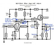
For starters, compare the tweaked setup to RCA's original. A regulated 250 VDC rail is the starting point.
BTW, the tweaked setup's grid leak biased 2nd gain block has the cathode at ground potential.
BTW, the tweaked setup's grid leak biased 2nd gain block has the cathode at ground potential.
Attachments

....what are the working voltages in pins 1, 3 and 6?
The gain-device "fights" the plate resistor.
If the tube were open, Vp would be Vsupply. If the tube were shorted, Vp would be near zero. Neither condition works good.
For "a fair fight", you expect similar voltages, so Vp is about half of Vsupply.
Like pro wrestling, we never get a fair fight; and don't need exact fairness. Also here V1a has the large 39K dropping resistor. My pencil-check of this stage suggests the plate may sit near 180V (due to large-ish Rk). Artsalo may have actual data. However for a smoke-test, anything from 1/4 to 3/4 of Vsupply is probably a working condition, especially in a phono preamp with small signal levels.
The total drop across the plate resistor can be used to estimate the cathode resistor voltage. Or the estimated plate-cathode voltage divided by Mu for a rough guess of cathode voltage. Vpk= 180 and Mu=100 gives 1.8V. Actually probably ~~0.6 times this or 1.1V.
These thoughts will work for 90% of the circuits you will meet. (Well, maybe 70% of the stranger things seen on DIYA, with added fancy-bits and odd details.)
The design is a progression from a very common RCA circuit. The original circuit lacked the ability to drive into pretty much any load. Other than that it was a staightforward workmanlike circuit.
The MOSFET output in the design Eli often boosts picks up the weight of the load and frees up the rest of the circuit to amplify and signal shape.
I haven't built it, but the original RCA design is probably out there in near millions of household record players - or would be if they were all still in use. Unless you are terribly picky about your RIAA curve (many are for better or worse) it is a relatively simple no frills build with all the usual caveats around amplifying low signals.
PCBs are available if you think it will help:I'd like to build a phono preamp and and I'm looking at building it. I was hoping someone had built it. I'm a newbie to building electronics and tubes, and was hoping to get some advice.
The Valve Wizard
Isn't this:Merlin - the shop page doesn't seem to have this pcb on it - just the 3-valve pcb.
Compact Phono PCB the RCA phonostage?
Details at:
The Valve Wizard
I got directed to a 'Featured Items' page first, so I had to pull down the menu to get to the HiFi PCBs.
Looks like that pcb board schematic isn't the same circuit.
It would be very easy to adapt that PCB to the tweaked RCA schematic. A jumper here, a value change there ... Very noteworthy is protective Zener D2. Field experience shows that is an essential item. FWIW, my preference is a 12 V. part.
Stop fretting about voltages. A regulated 250 VDC B+ rail is the key item. Please notice that the RCA original only specifies the B+ rail value too. 12AX7/ECC83 section plate current is in the 900 μA. to 1 mA. range.
The 2nd gain block in the Tweaked RCA Setup is grid leak, AKA contact, biased. Something on the order of a 2 V. contact potential is associated with the 20 megohm grid leak resistor.
Between the buffering FET and grid leak biasing, 2 of the 3 "weak" spots found in the RCA original are shored up. The tweaked setup has better drive capability and improved bass extension. The 3rd weakness is the high CMiller of the 'X7 triode, which is intrinsic to the type. Select a cartridge or SUT that doesn't adversely interact with that capacitance.
Attachments

")
How would you know when selecting a cartridge If there is an issue?The 3rd weakness is the high CMiller of the 'X7 triode, which is intrinsic to the type. Select a cartridge or SUT that doesn't adversely interact with that capacitance.
Hey guys. Any idea if you need separate B+ rails for the 2 channels or whether you can use one rail with the 250v, 15k, 30uf, 39k, 30 uf and then feed the two channels from that. I'm getting very close to building this preamp. I've got all the components and thinking about layout now.
Greg
Each channel has its own set of decoupling parts. A single power trafo, rectifier, and filter is fine. Use individual LR8 regulators in each channel.
A schematic for a modest cost/high performance PSU is provided.
A schematic for a modest cost/high performance PSU is provided.
Attachments
- Status
- This old topic is closed. If you want to reopen this topic, contact a moderator using the "Report Post" button.
- Home
- Amplifiers
- Tubes / Valves
- Eli Duttmann's phono preamp voltages