About the gm value of the cascode device (the PNP transistor in a shunt cascode).
The bipolar transistor measures and sounds better than any other device, because of the higher gm. Choosing one with a low Cob is helpful for bandwidth in high-gain designs, and a high and stable beta helps with low distortion. The ZTX558 and the Fairchild KSA1381E are worth adding to your basket, if your are at Farnell or Mouser for parts.
You can compare measurement and sound of a series cascode with different devices in the upstairs position, like FETs and triodes, against a bipolar (NPN in the case of series cascode). I found that that even low-Hfe non-optimal NPNs were better than triodes/FETs.
With a practical high-gain stage, there is little need to worry about the gm. Running 1 to 5mA in the PNP is fine. The spectrum of the driver stage in my post above was taken with about 4mA of idle current in the PNP - a ZTX558.
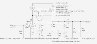
I'd like to make a couple of boards for a basic folded cascode to use in future projects. Does anyone have any comments on the below two options? The MOSFET CCS is certainly simpler, but the BJT ring of two might be more widely available.
Also interested to hear whether this use of LR8 makes sense. I haven't played with these before but it looks like it could make a pretty simple voltage reference here.
This will also be my first time creating boards so any helpful tips would be very appreciated.
edit: not sure if I'd keep the trim pots, btw. probably add a way to bypass them or replace after adjustment in circuit.
Also interested to hear whether this use of LR8 makes sense. I haven't played with these before but it looks like it could make a pretty simple voltage reference here.
An externally hosted image should be here but it was not working when we last tested it.
This will also be my first time creating boards so any helpful tips would be very appreciated.
edit: not sure if I'd keep the trim pots, btw. probably add a way to bypass them or replace after adjustment in circuit.
but I need to add a low-frequency servo at some point, to avoid the need to occasionally adjust the current-source.
Hi there Rod,
I just noticed your above comment. Why the need to readjust the current source?
Hi there Rod,
I just noticed your above comment. Why the need to readjust the current source?
Hello Ian!
Yes, with very high gain stages, that also requires large output swings: the output must stay near to half the anode voltage, or the available swing is diminished. The stability is very good if you use high quality parts and a stable base drive, but when you need swings amounting to most of the base/anode voltage, adjustment of the idle position might be needed from time to time. Mine need doing at the start and end of summer (that brief interval of the UK calendar). With lower gain or required swing, and especially your RIAA stages, it won't be needed.
My thoughts - some changes are needed:I'd like to make a couple of boards for a basic folded cascode to use in future projects. Does anyone have any comments on the below two options? The MOSFET CCS is certainly simpler, but the BJT ring of two might be more widely available.
Also interested to hear whether this use of LR8 makes sense. I haven't played with these before but it looks like it could make a pretty simple voltage reference here.
This will also be my first time creating boards so any helpful tips would be very appreciated.
edit: not sure if I'd keep the trim pots, btw. probably add a way to bypass them or replace after adjustment in circuit.
1. The Q1 PNP base-protection diode is mandatory;
2. Anode stopper, noted above, highly recommended, to avoid need to chase instabilities in this high-gain stage;
3. Bipolar current source degrades the power supply isolation, and will oscillate on its own, as drawn. The MJE350 C-E is drawn reversed. The DN2540 cascode is easy to use, and is well-worth the inclusion.
4. LR8 uses a band-gap reference, and is not intended for low-noise applications. This kind of regulator is relatively noisy, and the noise increases with output voltage, so beware excessive noise, especially in RIAA applications, where I suspect it will not be quiet enough.
5. Layout: short trace lengths, especially around Q1. Leave reasonable gaps from B and E of Q1 to low-voltage nodes, to avoid leakage risk.
My current version includes a discrete low-noise shunt regulator for the base, for use in driver or RIAA stages. DN2540 cascode is included. The rest of the boards in the lot are available - Rod Coleman Shunt Cascode - Power Tube Driver
Rod,
Thank you so much for the feedback!
1. I will add this; thank you.
2. I was thinking this would be off the board, but maybe I'm misunderstanding. This is a stopper b/w tube anode and the BJT/CCS junction?
3. Doh on the MJE350 c-e. I'm leaning now towards a depletion MOSFET anyways to keep things simple. I've used 10M45S more in the past but have nothing against DN2540 other than I don't think I have any atm.
4. I'll research LR8 noise a bit more and/or other options. Seems a shunt arrangement (like you mentioned) is a good option. Initially I was thinking a 0D3 would make a very 'pretty' voltage reference, but it doesn't jive well with the board and keeping connections short.
5. Noted, thank you again. I'm planning to cut my teeth on a CCS board or two and then trying a folded cascode board. I have not done boards in the past but I'm starting to enjoy the layout process.
When you mentioned your board earlier, I Googled it to see if you were making it available for purchase. Not finding anything, I started down this road. I hope you don't take my project as any kind of comment on what you've already done! Apparently I'm just not good enough at Google. Now that I've built up some thought inertia in this direction, I'll try to see the board project through.
Maybe a better option for a voltage reference
An externally hosted image should be here but it was not working when we last tested it.
Yes, with very high gain stages, that also requires large output swings: the output must stay near to half the anode voltage, or the available swing is diminished. The stability is very good if you use high quality parts and a stable base drive, but when you need swings amounting to most of the base/anode voltage, adjustment of the idle position might be needed from time to time. Mine need doing at the start and end of summer (that brief interval of the UK calendar). With lower gain or required swing, and especially your RIAA stages, it won't be needed.
Thanks Rod. I understand that side of the equation but really was asking about the root of change in circuit performance that necessitated the adjustment.
Framing it between summer start and end is interesting. What's the change, humidity ? I assume you have heating at home, or perhaps that's what the tube amp is for?
Seriously, at first read of your original mention, I'd wondered if it was due to changes in the 6Э5П's emission.
Been doing some reading up on voltage reference noise. Here's a great thread:
Some noise measurements for LEDs and zener diodes
Jones also has a nice section of zener and gas reg measurements.
I'm thinking one of the following options:
1 - TL431 like shown above, see TubeCAD (cons: noisy band pass reference, complicated, current requirements)(pros: easily adjustable bias and accuracy based on the resistor tolerance)
2 - Resistor with CCS to pull up voltage, see Bartola (cons: needs adjustment to reach correct bias voltage, lots of BJTs)(pros: low noise, low current)
3 - Zener with CCS load (cons: must find a quiet zener @ ~150V, increase current ot lower noise)(pros: simple, two terminal reference can swap in gas reg when noise is not critical)
references
1 T-Rex 300B Amplifier
2 http://www.bartola.co.uk/valves/2016/11/27/6э5п-shunt-cascode-driver/
3 Jones
Anyone care to comment on the above approaches?
I found that a Cascoded CCS with a top depletion FET and a lower J112 instead of the LND150 has much better temco. I run the J112 at about 1-1.4mA. You can implement a simple follower and reduce component number.
If you want to go better, then a shunt regulator as recommended by Rod is a good option
If you want to go better, then a shunt regulator as recommended by Rod is a good option
Great thanks for the update on your circuit!
By shunt regulator, are we talking about just a zener and transistor combo with a dropping resistor/ccs? Forgive my density. I'm still learning some of the common transistor arrangements (especially pnp coming from a tube perspective).
By shunt regulator, are we talking about just a zener and transistor combo with a dropping resistor/ccs? Forgive my density. I'm still learning some of the common transistor arrangements (especially pnp coming from a tube perspective).
Just going with a CCS + resistor (which several people are mentioning), I'm arriving at the following:
I'm planning to have some boards made up for my use and appreciate any suggestions for changes.
Initially I'd like to use this in the front end of an amplifier (hence the differential question that started the thread) but wouldn't mind trying it in an RIAA at some point, too.
An externally hosted image should be here but it was not working when we last tested it.
I'm planning to have some boards made up for my use and appreciate any suggestions for changes.
Initially I'd like to use this in the front end of an amplifier (hence the differential question that started the thread) but wouldn't mind trying it in an RIAA at some point, too.
Just going with a CCS + resistor (which several people are mentioning), I'm arriving at the following:
An externally hosted image should be here but it was not working when we last tested it.
I'm planning to have some boards made up for my use and appreciate any suggestions for changes.
Initially I'd like to use this in the front end of an amplifier (hence the differential question that started the thread) but wouldn't mind trying it in an RIAA at some point, too.
Should be worth some tests and measurements, at least! Measure the base when running large swings - getting the tightest grip on the base is important for the measured performance, and the sound. But it should be low enough noise.
One thing needs a correction: diode D1 is reversed. It needs to protect the PNP from violations of VEBO, which is usually only -5V or so. The circuit may well start up with more voltage on the base, and exceeding this rating has the annoying outcome of leaving the PNP functional, but with degraded noise and gain.
Thanks Rod. I understand that side of the equation but really was asking about the root of change in circuit performance that necessitated the adjustment.
Framing it between summer start and end is interesting. What's the change, humidity ? I assume you have heating at home, or perhaps that's what the tube amp is for?
Seriously, at first read of your original mention, I'd wondered if it was due to changes in the 6Э5П's emission.
Yes, the house gets a bit colder in my hifi den. It can't be helped - the house was designed for heating with open fires, and now it's in a statutory «Conservation Area» - so any construction-hacks have to be kept invisible. The amps are near a gapless 9 inch wall, and they sit on a ventilated wooden floor. Proper 19th century squalor!
6Э5П's emission is solid, with time or temperature. But like most MOSPower devices, the DN2540's Vgs running value shifts enough over 10°C to be measurable.
Here's a pass at a board. I have not made boards before, but once I started it was kind of intuitive (like virtual p2p). It it a little tight around Q6, the follower for the voltage reference. The emitter trace crosses under the base trace, but they are roughly the same voltage.
Dimensions are 3.75" x 2". Big cap spacing is 27.5mm and most of the resistors are 1/2W (except v-ref, led dropper, output). Room for a large heatsink (based on Aavid/Ohmite datasheet dimens).
An externally hosted image should be here but it was not working when we last tested it.
Dimensions are 3.75" x 2". Big cap spacing is 27.5mm and most of the resistors are 1/2W (except v-ref, led dropper, output). Room for a large heatsink (based on Aavid/Ohmite datasheet dimens).
Looks good! As I said the LND150 tempo is poor even when run at 500uA) so best to change it for a J112 and run it at 1mA. It will provide a more stable voltage. Otherwise will drift when hot
Also the anode DN2540 on its own is not the best CCS when running hot. Again, best is to have a cascode pair. The device on the top will take the heavy load and the below device will set the current and run cooler, hence more stable with temperature
I’d rather use an IXTP08n100d at the top, will allow the lower device to operate in better conditions.
Ale
One more practical suggestion:
Instead of using the raw TO-92 PCB footprint, which places the base and collector much too close for easy soldering without shorts, let alone the high-voltage swing across them (case of the cascode PNP): use an "ammo-pack" TO-92 pattern. These put the pads on a 0.1" [2.54mm] pitch, and make life much easier. Form the leads to suit when stuffing. Many transistors are available on cut strips of ammo tape, ready to go right into those holes.
Instead of using the raw TO-92 PCB footprint, which places the base and collector much too close for easy soldering without shorts, let alone the high-voltage swing across them (case of the cascode PNP): use an "ammo-pack" TO-92 pattern. These put the pads on a 0.1" [2.54mm] pitch, and make life much easier. Form the leads to suit when stuffing. Many transistors are available on cut strips of ammo tape, ready to go right into those holes.
- Status
- This old topic is closed. If you want to reopen this topic, contact a moderator using the "Report Post" button.
- Home
- Amplifiers
- Tubes / Valves
- Folded/shunt cascode differential question