Hey everyone, been lurking the forums for a while and finally had something worth posting about.
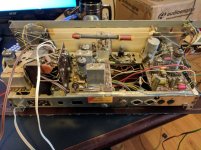
A while back I picked up a nice looking German console radio from the what I guess is the late 60s. The unit is in awesome shape and powers on and works, but unfortunately after a few minutes the sound starts to distort badly. Well today I decided that I am going to fix it maybe even upgrade the speakers a bit. I pulled the electronics out to take a look and need some advice on where to start as tubes are fairly new to me outside of the guitar world. So I am not sure if I should replace caps, tubes, both, none etc. I can tell you that the large can cap is blown, this one reads 50+50/350v, I can find a replacement in 500v, but not 350v, this is the only part that I know must be replaced. The tubes dont show any signs of failure but I can only assume are pretty weak at this point. It has the following tubes: ECC85, EZ80, ECH81, EBF89, ECC83, and a ELL80. I priced out replacements and it looks like it will be around $130. I also noticed that telefunken tubes cost quite a bit more than others, and most of the tubes in it are telefunken. Should I replace all of them with whatever is available, or am I better off getting them tested and only replacing the ones that need it, or should I just replace that big cap and see how it does after? What about the other caps on the board? Most of them are ERO FOL II's and I have read that it is hard to find a decent replacement for those. What are your guys thoughts on it?
Thanks
Last edited by a moderator:
I would advice you not to randomly replace tubes, but to try and find out what is going on.
Chances are that people on old radio restoration forums can provide you with the service documentation. You can then compare bias points with what is written in the documentation and get an idea of where things go wrong - assuming you have a multimeter, but a simple multimeter is far cheaper than 130 dollars.
I can't open your pictures, but if the capacitor across the secondary of the mains transformer or the coupling capacitors to the control grids of the ELL80 are paper capacitors, it is a good idea to replace those as a precaution. Old paper capacitors are notorious for their leakage currents.
One old radio restoration forum is Nederlands Forum over Oude Radio's. It is in Dutch, but they also accept contributions in English. Since it is a German radio, you could also try to find a German forum.
Last edited:
Thanks guys, hope these pictures work better. I also found this: Stereo-Gerat 25506 Radio Silva Tonmobel, Silva-Schneider; Sa, its not the same console, but the electronics are the same so I have downloaded the schematics for it.
Attachments
A good thing to check first is the bias voltage at the control grids of the ELL80.
Assuming that the grids are connected to ground by grid leak resistors, the DC bias voltage should be very close to ground level and stay very close to ground level (say between 0 and 0.2 V). If the voltage should become too high, that could cause distortion, damage to the ELL80 and damage to the EZ80, so you definitely want to know that as soon as possible.
Two possible causes of too high control grid voltages are leakage of the DC blocking capacitors and a faulty ELL80 that suffers from grid emission. Grid emission in a faulty tube only starts once the grid has become hot, which is some time after the cathode has heated up. That seems to match your description, but there are many other possible faults that could lead to distortion after a few minutes.
I think my first action is going to replace the caps then, and leave the tubes alone. Ive been putting together a list of replacement values and have one I cant figure out what voltage. Its a .022uf and the only other marks on it are 10/160. Also, the the big can mulit cap is 50+50 350v. Would a 50 + 50 500v be a sutible replacement?
Also, the the big can mulit cap is 50+50 350v. Would a 50 + 50 500v be a sutible replacement?
As long as the part fits mechanically, going up in WVDC is fine. Never go down in WVDC.
First thing is to find out where the issue is located. After having replaced the faulty mains filter cap, set the device into TA mode (most probably it has a switch named such) and apply audio signal to the turntable input socket at the back. Does it still distort? In one or in both channels? If so, the AF section is faulty. If it is in both channels, have a look at the ELL80's common cathode electrolytic (100µF/35V) and/or the (expensive!) tube itself. If it is in one channel only, the grid coupling cap of the related pentode section might be leaky.
If not, it's the RF or IF section, which may become some major problem to fix.
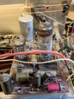
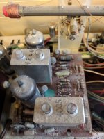
Btw, those Roederstein EROFOL II capacitors aren't paper caps at all. No need to replace them just by suspicion, 'cause they usually are very reliable. But have a careful search for EROID or WIMA Durolit capacitors and replace these. I suppose there might be a Durolit on the AF (ECC83/ELL80) board, next to that big 0,15 µF EROFOL II, and another one that is hidden by this red screened wire, but your pics doesn't show it exactly.
Best regards!
If not, it's the RF or IF section, which may become some major problem to fix.
Btw, those Roederstein EROFOL II capacitors aren't paper caps at all. No need to replace them just by suspicion, 'cause they usually are very reliable. But have a careful search for EROID or WIMA Durolit capacitors and replace these. I suppose there might be a Durolit on the AF (ECC83/ELL80) board, next to that big 0,15 µF EROFOL II, and another one that is hidden by this red screened wire, but your pics doesn't show it exactly.
Best regards!
Last edited:
It is a midrange stereo console with electrostatic tweeters and a comparatively weak (for the time) audio amplifier. The chassis seems to be a rebadgeted Körting. It should be pretty easy to restore and you are on the correct path, but don't expect Hi-Fi quality. I try to keep the originality by disconnecting the main filter cap from the circuit but leaving it there; I then add multiple modern 400 or 450V caps of the correct value on the underside of the board. As alternative, new multisection capacitors with the exact same style are sold by Frag´ Jan Zuerst, at higher price.
On my experience, the capacitors around the ELL80 or the "modern" replacement ECLL800 are usually degraded by the very high temperature of this tube. The 100uF cathode capacitors C905 and C1103 must be replaced. The 0.022 uF coupling capacitors may be replaced but they are usually still good on this type of radios.
On my experience, the capacitors around the ELL80 or the "modern" replacement ECLL800 are usually degraded by the very high temperature of this tube. The 100uF cathode capacitors C905 and C1103 must be replaced. The 0.022 uF coupling capacitors may be replaced but they are usually still good on this type of radios.
Last edited:
I try to keep the originality by disconnecting the main filter cap from the circuit but leaving it there; I then add multiple modern 400 or 450V caps of the correct value on the underside of the board.
On my experience, the capacitors around the ELL80 or the "modern" replacement ECLL800 are usually degraded by the very high temperature of this tube. The 100uF cathode capacitors C905 and C1103 must be replaced. The 0.022 uF coupling capacitors may be replaced but they are usually still good on this type of radios.
That was exactly my plan with the main filter cap after not finding a suitable replacement in size/mounting. Luckily for me, I ordered replacements for the 100uf and .022uf caps as well.
Thanks!
after idling for a few minutes I got 1v and 0v on the control grid pins of the ELL80. Does that 1v mean its bad? Or I guess that the caps could need replacing as well, most of them look to be paper.
Thanks
When it's still 1 V with the coupling capacitor disconnected or replaced by a known good one, then it is probably the ELL80 - although it could then still be a dirty tube socket or so.
When it drops very close to 0 V with the coupling capacitor disconnected or replaced by a known good one, then it was the coupling capacitor.
Got the replacement parts in and installed them. Through the TA input in which I am using a 5pin din to rca adapter, I got around 5 minutes of decent sound which I was happy with, then it started to distort again. Distortion was on both channels. So far I have replaced the filter cap, and what I think are the coupling caps, but I am not sure. On the schematic, they are C902, C903, C905, C1002, and C1003. I am still getting 1 and 0 volts at the control grids of the ELL80. Oh, I also replaced R1102 and R1101 since they did not test to spec.
Attached are the schematics
Attached are the schematics
Attachments
The grid leak resistors R903 and R1003 are not connected to ground, but to a -14 V rail, according to the schematic. That means that the bias voltage at the grids is supposed to be -14 V.
What kind of meter did you use (can affect the result through voltage division with R903 / R1003)?
What voltages do you see when you measure across R903 and R1003?
Is there 14 V across C1103?
What kind of meter did you use (can affect the result through voltage division with R903 / R1003)?
What voltages do you see when you measure across R903 and R1003?
Is there 14 V across C1103?
The schematic is somewhat unusual and therefore confusing.The grid leak resistors R903 and R1003 are not connected to ground, but to a -14 V rail, according to the schematic. That means that the bias voltage at the grids is supposed to be -14 V.
The -14V is developed ascoss R1103+R1104 by the current from the radio-part, has nothing to do with the amp-section.It is used by an (optional ?) stereodecoder.
The bias voltage is on R1004 ~7volts.
Mona
- Status
- This old topic is closed. If you want to reopen this topic, contact a moderator using the "Report Post" button.
- Home
- Amplifiers
- Tubes / Valves
- Fixing 60's German tube amp