A C- (bias) supply is a low current situation. Only a few mA. flow, when the NET voltage on the grids approaches zero. Combine those few mA. with the losses in the trim pots. and you have the requirement. From a practical standpoint, rail voltage (which is design dependent) is the critical number.
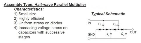
Many power trafos have a bias tap on the rectifier winding that is 1/2 wave rectified. A spare filament winding can be voltage multiplied to generate the volts needed. As this is a negative rail, reverse the diode polarity shown in the uploaded graphic. Use Schottky diodes to minimize forward drop losses, along with being "noise free".
Many power trafos have a bias tap on the rectifier winding that is 1/2 wave rectified. A spare filament winding can be voltage multiplied to generate the volts needed. As this is a negative rail, reverse the diode polarity shown in the uploaded graphic. Use Schottky diodes to minimize forward drop losses, along with being "noise free".
Attachments
Look at the 6C33C datasheet. Notice, the 200 Kohm grid to ground resistance limit, which may be for self biased arrangements. The type is extremely vulnerable to runaway. "Fixed" bias exacerbates the runaway character of tubes. If you employ combination bias, with a relatively small portion of the TOTAL bias voltage coming from a RC network, the operating point is stabilized.
Arrange your driver circuitry so that a 47 Kohm grid to gound resistor is not problematic and "stand" the cathode on a 100 Ω/470 μF. network. The RC network stabilizes the operating point and provides a convenient "idle" current test point.")
Arrange your driver circuitry so that a 47 Kohm grid to gound resistor is not problematic and "stand" the cathode on a 100 Ω/470 μF. network. The RC network stabilizes the operating point and provides a convenient "idle" current test point.
...200 Kohm grid to ground resistance limit...
It is a Pass Tube. In the intended application, the load it is powering is in-effect a giant cathode resistor. The pass tube can't flow more than the load will take. And typically a pass tube driver has large down-swing to throttle a runaway.
Considering that lesser tubes spec 50K in fix-bias, I agree this monster should not be near 200K except with mostly cathode bias.
Thank you!Arrange your driver circuitry so that a 47 Kohm grid to gound resistor is not problematic and "stand" the cathode on a 100 Ω/470 μF. network. The RC network stabilizes the operating point and provides a convenient "idle" current test point.
- Status
- This old topic is closed. If you want to reopen this topic, contact a moderator using the "Report Post" button.
- Home
- Amplifiers
- Tubes / Valves
- Fixed bias PSU questions