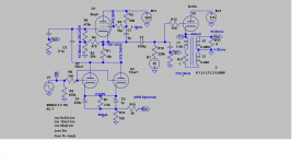
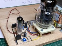
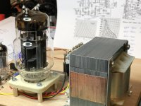
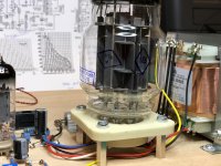
I recently reworked on 6c33c cathode output amp which I built years ago. I ordered a M5 iron which has Pri 200 Ohms and Sec 4/8/16,but the high frequency (above 5k) rolled off quite bit, and I have rewired the primary wiinding to a secondary winding to increase the negative feedback so the frequency is significanlty improved. I use a vintage Pioneer CL-70 90dbs speaker, the sound is really very good.
The driver was originally SV83 and 6n1p by Svetlana. I use 6p14p (el84/6bq5) and 12ax7 with slight changes in components values as shown. It's 250V or half the HT for bottom and top tubes. The driver distortion is 1% and power output is <2% without NFB.
The libs are zips file found on this forum, found it is quite accurate as compared to actual circuit measurement, I post here for reference.
*
* Generic triode model: 6C33CB
* Copyright 2003--2008 by Ayumi Nakabayashi, All rights reserved.
* Version 3.10, Generated on Sat Mar 8 22:39:32 2008
* Plate
* | Grid
* | | Cathode
* | | |
.SUBCKT 6C33C A G K
BGG GG 0 V=V(G,K)+1
BM1 M1 0 V=(0.31995431*(URAMP(V(A,K))+1e-10))**-1.9846926
BM2 M2 0 V=(0.43045404*(URAMP(V(GG)+URAMP(V(A,K))/1.7800853)+1e-10))**3.4846926
BP P 0 V=0.015432878*(URAMP(V(GG)+URAMP(V(A,K))/4.1353667)+1e-10)**1.5
BIK IK 0 V=U(V(GG))*V(P)+(1-U(V(GG)))*0.026902304*V(M1)*V(M2)
BIG IG 0 V=0.0077164388*URAMP(V(G,K))**1.5*(URAMP(V(G,K))/(URAMP(V(A,K))+URAMP(V(G,K)))*1.2+0.4)
BIAK A K I=URAMP(V(IK,IG)-URAMP(V(IK,IG)-(0.013640208*URAMP(V(A,K))**1.5)))+1e-10*V(A,K)
BIGK G K I=V(IG)
* CAPS
CGA G A 31p
CGK G K 30p
CAK A K 10.5p
.ENDS
Attachments
Last edited:
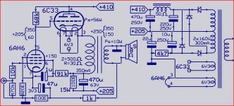
Antique Sound Lab KI22-FOX Stereo, The Antique Sound Lab KI22-FOX Stereo Integrated Amplifier by Dick Olsher
That is the amp what I am trying to build initially (if anyone still has copy of schematic please post it here for sharing), the problem is difficulty the output transformer needs to be custom ordered (again).
I could have seen it at the time when I built it, but I am not a bit fan of DC the amp, I don't use DC in OTL amp like Tim Mellow amp, I believe the cap coupled should sound just as good. Once you're DC you can't easy changed, but need to concentrate on sonic improvement in the overall schematic, the cap coupled allow you to make change without realigned the opertion point and bias.
The Pdissp is 56W for Mona sch, try to reduce it if you're going to build it. It's not a zero feedback amp, with pentode driver the distortion is higher than Mu stage. Try to SIM it to better understand the circuit.
I was looking at this one actually, price is about 100 euros.
LO-SE50-1 Transformator głośnikowy SE - Lampy Elektronowe On-Line. Największy polski sklep z technik
LO-SE50-1 Transformator głośnikowy SE - Lampy Elektronowe On-Line. Największy polski sklep z technik
DHTRob - Single Ended 6C33C with D3A driver
It is good for anode output SE, but 31H Pri inductance is probably too high for cathode output which is expected about 7-8H. If you plug in the inductance 31H and Sec 0.4H in SIM, the frequency (response above 5Khz) rolled off very fast, and for 7-8H Pri, rolled off above 10Khz quite a bit difference there.
@Koon,
Modeled the design I posted earlier, but something doesn't add up, I've been staring at it for the past 30mins and checked all the models (pin assignment etc.) but can't get it to work? The fact that I have some nodes with fV showing must have something to do with it
Perhaps you have some pointers?
File 6AH6.inc
File 6C33.inc
Modeled the design I posted earlier, but something doesn't add up, I've been staring at it for the past 30mins and checked all the models (pin assignment etc.) but can't get it to work? The fact that I have some nodes with fV showing must have something to do with it
Perhaps you have some pointers?
File 6AH6.inc
.SUBCKT 6AH6 1 2 3 4 ; P S G K
+ PARAMS: MU=49.9 EX=1.39 KG1=632 KP=162 KVB=8 VCT =0; KG2=415
+ CCG=11P CPG1=.015P CCP=5P RGI=2K
RE1 7 0 1MEG ; DUMMY SO NODE 7 HAS 2 CONNECTIONS
E1 7 0 VALUE= ; E1 BREAKS UP LONG EQUATION FOR G1.
+{V(4,3)/KP*LOG(1+EXP((1/MU+(VCT+V(2,3))/V(4,3))*KP))}
G1 1 3 VALUE={limit((PWR(V(7),EX)+PWRS(V(7),EX))/KG1*1.57*ATAN(2*V(1,3)/(KVB*3.14159)),0,v(1,3)/3200)}
;change /710 to /670, change the slope
; added limit-better models lower plate voltage limit condion
G2 4 3 value= {(I(G1)*900/(V(1,3) +2800))}
RCP 1 3 1G ; FOR CONVERGENCE
C1 2 3 {CCG} ; CATHODE-GRID 1
C2 1 2 {CPG1} ; GRID 1-PLATE
C3 1 3 {CCP} ; CATHODE-PLATE
R1 2 5 {RGI} ; FOR GRID CURRENT
D3 5 3 DX ; FOR GRID CURRENT
.MODEL DX D(IS=1N RS=1 CJO=10PF TT=1N)
.ENDS
File 6C33.inc
.SUBCKT 6C33 A G K
BGG GG 0 V=V(G,K)+1
BM1 M1 0 V=(0.31995431*(URAMP(V(A,K))+1e-10))**-1.9846926
BM2 M2 0 V=(0.43045404*(URAMP(V(GG)+URAMP(V(A,K))/1.7800853)+1e-10))**3.4846926
BP P 0 V=0.015432878*(URAMP(V(GG)+URAMP(V(A,K))/4.1353667)+1e-10)**1.5
BIK IK 0 V=U(V(GG))*V(P)+(1-U(V(GG)))*0.026902304*V(M1)*V(M2)
BIG IG 0 V=0.0077164388*URAMP(V(G,K))**1.5*(URAMP(V(G,K))/(URAMP(V(A,K))+URAMP(V(G,K)))*1.2+0.4)
BIAK A K I=URAMP(V(IK,IG)-URAMP(V(IK,IG)-(0.013640208*URAMP(V(A,K))**1.5)))+1e-10*V(A,K)
BIGK G K I=V(IG)
* CAPS
CGA G A 31p
CGK G K 30p
CAK A K 10.5p
.ENDS
Attachments
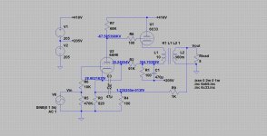
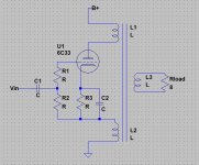
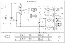
In the meantime I have made some drafts with ideas so might as well share those here as well, so perhaps we'll get some discussion going. What I was aiming for is maximum coupling between the 6C33 and the OPT and reducing the drive requirement for the input stage with 6c33_se_005.jpg.
6c33_se_002.jpg
Incorporating a 2nd primary winding into the design, auto-bias.
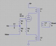
6c33_se_003.jpg
Incorporating a 2nd primary winding into the design, fixed-bias.
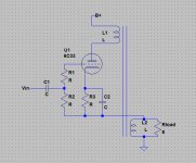
6c33_se_004.jpg
Incorporating the secondary winding into the design, auto-bias.
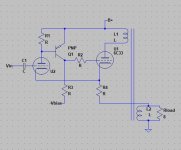
6c33_se_005.jpg
Incorporating the secondary winding into the design, fixed-bias and making it easier to drive with a circuit proposed by J. Broskie.
6c33_se_002.jpg
Incorporating a 2nd primary winding into the design, auto-bias.
6c33_se_003.jpg
Incorporating a 2nd primary winding into the design, fixed-bias.
6c33_se_004.jpg
Incorporating the secondary winding into the design, auto-bias.
6c33_se_005.jpg
Incorporating the secondary winding into the design, fixed-bias and making it easier to drive with a circuit proposed by J. Broskie.
Attachments
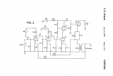
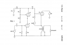
This is relevant too, especially considering driving the 6C33.
Patent US5859565 - Cathode-follower high-fidelity power amplifier - Google Patents
Patent US5859565 - Cathode-follower high-fidelity power amplifier - Google Patents
Attachments
@Koon,
Modeled the design I posted earlier, but something doesn't add up, I've been staring at it for the past 30mins and checked all the models (pin assignment etc.) but can't get it to work? The fact that I have some nodes with fV showing must have something to do with it
Perhaps you have some pointers?
File 6AH6.inc
File 6C33.inc
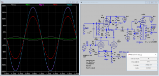
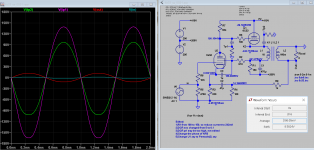
1) Use Pentode2.asy with the correct pin is easiest, tetrode.asy doesn't seem to work. The model is working. You can also change the pin order in inc file to match the pentode.asy you have.
But
2) The phase for NFB is incorrect, try to change the phase of Pri or Sec.
3) Try to reduce the Pdissp of 6c33c
Attachments
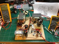
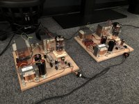
In the meantime I’ve put a prototype together and plan to finsh the PSU for it tomorrow, as all that simulation is nice, but there’s but one proof of the pudding afterall, which means actually building it!
Attachments
Last edited:
- Status
- This old topic is closed. If you want to reopen this topic, contact a moderator using the "Report Post" button.
- Home
- Amplifiers
- Tubes / Valves
- 6C33C cathode output amp rewoked