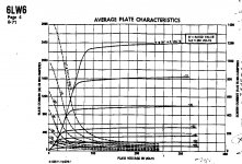
But 105mA Peak. The most peak in the smallest bottle of any TV-shop tube.
<snip>
PRR,
Thank you for all the great information.
My comment about the 1030/30 was just a wild-*** guess. I am not yet capable of making accurate calculation on audio amplifiers. I am trying to learn as I go but most times, I must lean on folks like yourself to help me through any issues I come across.
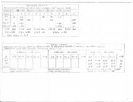
The preferred speakers were wired for 32 ohms. According to the gain charts, 16 ohm and 22 ohm drivers were also acceptable.
I'll post the schematics and charts, shortly (I think you will find them interesting). A review and any comments would be appreciated.
Hi Kasanay, do you have any documentations that we can look at? links?
Tony,
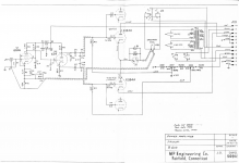
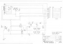
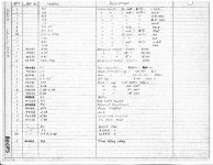
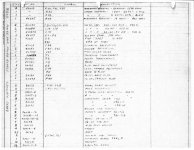
Here are the schematics, parts lists and charts.
If you are familiar with the Futterman family of OTL amps, you will see these are very similar to the 12B4 amps he built. I think the biggest difference can be seen in the power supplies (and the number of tubes).
Thanks,
Joe Y
Attachments
Presumably it is based on the Futterman design. I imagine all of those electrolytics now need to be replaced, and there are a lot of them.
It probably sounded pretty good, no one would have gone to this amount of trouble at that time for any other reason.
Kevin,
As I posted in another reply, these are VERY similar to the the Futterman 12B4 amps.
MP was building these at (basically) the same time that Julius was building his.
Thanks,
Joe Y
Looks like it says:
MP Engineering Co. Fairfield ? Conn. <snip>
Smoking-amp,
There are no fans on the amps.
These were indeed, marketed (to a few very wealthy people). Mirko Paynko designed, built and installed these and many other systems in fine homes and institutions across the country. He was in business from the 30' until some time in the 60s.
Thanks,
Joe Y
You are right of course, it CAN be done. <snip>
Don't discount this design too quickly. I know a fellow who ran his amps for many years. I don't know how reliable they were, but this fellow has the means to replace them with any system on the market if he wanted.
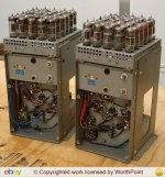
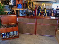
The photos attached show a similar pair of MP OTLs that were sold on the bay a few years ago. The second shot is of a pair that are owned by Mathew Polk of Polk Audio. He reportedly prefers these over several others at his disposal.
Thanks for your interest,
Joe Y
Anybody interested in learning a little about the guy that designed these amps, check out the story in the Sept 1957 High Fidelity mag. The piece is called: Music For Millionaires. I think it starts on page 55.
Do a search for: "Music for Millionaires Mirko Paneyko"
Thanks,
Joe Y
Attachments
MP OTL amp and J.Futterman amp are topologically very similar, but main difference between two OTL amps is that by MP amp phase inverter cathode resistor (R7=33K) is grounded , where by Futterman amp that cathode resistor is purposely connected to output line of the amp ,
IMHO those vintage MP OTL amps deserve and need very careful check of all active and passive elements,correct OPS biasing ,...
---------------------------------
and Happy New Year to everybody !
IMHO those vintage MP OTL amps deserve and need very careful check of all active and passive elements,correct OPS biasing ,...
---------------------------------
and Happy New Year to everybody !
Don't discount this design too quickly.
Sorry if I sounded too harsh. I'm sure the MPs CAN indeed sound excellent, just saying that's not the way I would (these days) design such an amplifier.
Once one resigns themselves to the use of massive N Fdbk, as pretty much all OTLs do in the end, to get lowered output Z, then one no longer needs to fixate on triode outputs. As Futterman realized in his H3 design, a big honkin' pentode is just fine. 6HJ5, then 6LF6, the bigger the better. Actually a Mosfet would work best if it only looked more like a tube.
I would be more oriented toward reliability, ease of servicing, and minimized heat and weight these days. (switching power supplies for sure)
-----------
MP OTL amp and J.Futterman amp are topologically very similar, but main difference between two OTL amps is that by MP amp phase inverter cathode resistor (R7=33K) is grounded , where by Futterman amp that cathode resistor is purposely connected to output line of the amp ,
Futterman H1 schematic for comparison:
http://www.audiodesignguide.com/otl/12b4.gif
This difference IS significant. Futterman used an (anti) bootstrap for the bottom output tube's drive ( 6S4 splitter cathode), to effectively "equalize" the grounded cathode mode drives for the outputs. (which requires either attenuation of the bottom grid signal for a totem pole design, or boosting of the top tube grid signal via (positive) bootstrapping.)
While the MP design does not do this. (it has equal splitter outputs) Which overdrives the bottom output tubes in a totem pole configuration. Bruce Rozenblit used the same configuration for his OTL design. That got criticized by John Broskie at TubeCad. It makes for inefficient operation of the output tubes, and higher distortion, 2nd harmonic distortion mainly. A SET like characteristic.
This probably does appeal to some listeners, just like SET designs do. However, the output tubes run hotter since they are fighting each other some. Output Z will not be as low either. My feeling is that the output stage (of an OTL) is not the place to meddle for such effects.
If massive N Fdbk is a religious problem however, then it'll take 600 12B4s for an 8 Ohm OTL with quality triode sound. (Or a triode emulation type design with some big pentode outputs. That's NOT triode strapped output pentodes by the way, Mosfets would work just fine too )
Last edited:
Here is the article.
Thank you for posting that for me.
I would not expect to need women with shopping-carts of tubes for hourly repairs. This is far smaller than EINIAC (20,000 vacuum tubes). I road-tripped tube power amps with more tubes total than this, and didn't carry spares, and no failed gigs. I salvaged a broadcast console with more tubes than this, and I do not recall tube-troubles in commissioning or operation.
This rig has a small advantage in that one or two 12B4s could fail and hardly be missed. (In a console, any tube failure was a dead channel or output; mitigated in that each stage was plug-out and also originally patchable.)
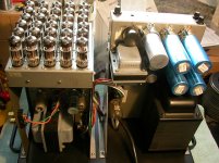
The tube density is frightful, yes. I commend the book Hot Air Rises and Heat Sinks, which discusses why many heat problems confound average persons. In particular, putting hot-spots together may *improve* cooling; or at least not get you in trouble. The convective forces and air-rate increase. His example was a rack of gear. One unit ran warm. Two units ran warmer. 13 units stacked ran *cooler* than 3 on average, with no over-temps.
I do not think "massive" NFB, not like a Williamson or transistor amp. I make it about 20dB in lower audio band and less above ~~1KHz.
Pentode power will need floating G2 supply, a complication the designer may have disliked.
Bootstrapping the driver to "equalize" the drives may be another complication avoided. Work out the gains. The "plate loaded" side has very low gain. The "cathode loaded" side has lower gain, but maybe not enough to hurt, or justify all possible "improvements". I'll accept that the designer spent a lot more time on this than I ever will, and his path was best for him. Apparently this was not a one-off or direct-to-dumpster product.
Bigger tubes mean less tubes but they cost more each. At some point in the designer's thinking, he studies his tube-shop price list. While the customers are rich, their pockets are not bottomless, and you want to give them the "most" for their money while not going broke. The wiring-costs of 30 small sockets vs 8 large sockets do suggest fewer bigger tubes, but you may have low-pay workers or just think socket-wiring is relaxing evening work. Certainly the wiring of 30 sockets looms small compared to the hundreds of hours developing and evaluation, and time spent turning potential customers into actual buyers.
An amazing piece of kit. Thanks for sharing.
This rig has a small advantage in that one or two 12B4s could fail and hardly be missed. (In a console, any tube failure was a dead channel or output; mitigated in that each stage was plug-out and also originally patchable.)
The tube density is frightful, yes. I commend the book Hot Air Rises and Heat Sinks, which discusses why many heat problems confound average persons. In particular, putting hot-spots together may *improve* cooling; or at least not get you in trouble. The convective forces and air-rate increase. His example was a rack of gear. One unit ran warm. Two units ran warmer. 13 units stacked ran *cooler* than 3 on average, with no over-temps.
I do not think "massive" NFB, not like a Williamson or transistor amp. I make it about 20dB in lower audio band and less above ~~1KHz.
Pentode power will need floating G2 supply, a complication the designer may have disliked.
Bootstrapping the driver to "equalize" the drives may be another complication avoided. Work out the gains. The "plate loaded" side has very low gain. The "cathode loaded" side has lower gain, but maybe not enough to hurt, or justify all possible "improvements". I'll accept that the designer spent a lot more time on this than I ever will, and his path was best for him. Apparently this was not a one-off or direct-to-dumpster product.
Bigger tubes mean less tubes but they cost more each. At some point in the designer's thinking, he studies his tube-shop price list. While the customers are rich, their pockets are not bottomless, and you want to give them the "most" for their money while not going broke. The wiring-costs of 30 small sockets vs 8 large sockets do suggest fewer bigger tubes, but you may have low-pay workers or just think socket-wiring is relaxing evening work. Certainly the wiring of 30 sockets looms small compared to the hundreds of hours developing and evaluation, and time spent turning potential customers into actual buyers.
An amazing piece of kit. Thanks for sharing.
PRR, what is your take on the Tim Mellows OTL? anyone?
http://www.mellowacoustics.com/articles/Tim_Mellow_25w_OTL_Tube_amplifier.pdf
http://www.mellowacoustics.com/articles/Tim_Mellow_25w_OTL_Tube_amplifier.pdf
I would not expect to need women with shopping-carts of tubes for hourly repairs. This is far smaller than EINIAC (20,000 vacuum tubes).
I have one, which I built several years ago. It has been extremely reliable and performs excellently.
I was speaking of the case of 600 12B4 tubes to obtain a quality 5X rp load line for the triodes.
That would be 1200 tubes for a stereo amplifier then.
The Tim Mellows OTL is using two BIG tubes per channel.
I commend the book Hot Air Rises and Heat Sinks, which discusses why many heat problems confound average persons. In particular, putting hot-spots together may *improve* cooling; or at least not get you in trouble.
One needs a "chimney" effect to improve air circulation with more heat. The MP amp has got the tubes on a flat plane, their density impairing easy air flow.
Bootstrapping the driver to "equalize" the drives may be another complication avoided. Work out the gains. The "plate loaded" side has very low gain. The "cathode loaded" side has lower gain, but maybe not enough to hurt, or justify all possible "improvements".
The gains would be around 3 bottom side (Mu 6.5 swamped by overloading) and less than 1 top side (cathode follower). An excellent 2nd harmonic generator I think. It would only take 2 resistors (the Futterman fix or the Technics "anti Futterman" fix) to fix this. This -could- be a "tube sound" choice by the designer. Not good for the already stressed tubes though, making them run hotter. The choice of using more tubes than Futterman's H1 does allow the use of reduced N Fdbk, but mis-matching the tube bank gains requires increased N Fdbk.
Bigger tubes mean less tubes but they cost more each.
It's not just socket wiring. Where are the bias adjustments for all those tubes? I only see one for the whole bank. So matched tubes are required there. I would be a really "pi__ed" customer if I had to order 60 matched tubes every time a few went out. It does look like all those tubes were ordered as a single batch from Raytheon. All it takes is one of those tubes to short out, and good-bye speaker.
If there really was some "military" aspect to this guys work, I would guess the CIA were planning to send this thing to "der Fuhrer", so he would be totally occupied with maintaining his sound system.
OK, anti high tube # OTL rant off. Some significant amount of TLC can likely bring back some nice sound. A few fixes might make good sense.
Last edited:
I was speaking of the case of 600 12B4 tubes to obtain a quality 5X rp load line for the triodes.
That would be 1200 tubes for a stereo amplifier then.
The Tim Mellows OTL is using two BIG tubes per channel.
Yes, my reply was to TonyTecson's question about the Tim Mellow OTL.
Yes.
Well we all look at things differently, so all opinions are always of interest. And I value PRRs comments fully as well. I just happen to be more economical and reliability minded about designs, 100 parallel 12AX7 tube amplifiers do get under my skin, for example. Some designs are obviously more about climbing Mt Everest, than about practicality. I would put the MP amplifier somewhere in the neighborhood of the old Chinese proverb: "May your journey be interesting." (never a dull moment)
Well we all look at things differently, so all opinions are always of interest. And I value PRRs comments fully as well. I just happen to be more economical and reliability minded about designs, 100 parallel 12AX7 tube amplifiers do get under my skin, for example. Some designs are obviously more about climbing Mt Everest, than about practicality. I would put the MP amplifier somewhere in the neighborhood of the old Chinese proverb: "May your journey be interesting." (never a dull moment)
Last edited:
Pictures??? (of the Bozaks in particular)
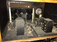
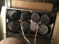
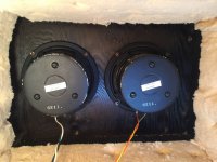
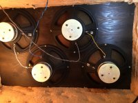
Here are some shots of the Bozak Speakers. The are wired to present a 32ohm load.
Each cabinet contains:
(4) 12" woofers
(2) 6.5" mids
(8) 2.25" tweeters
(1) Jensen 302 super-tweeter
(2) crossover networks
Attachments
")
The speakers look really nice!
Just tossin' an idea out here: You are apparently short of 12B4 tubes to fill all the sockets, and buying new ones would require 60 new matched ones.
You could use all the tubes you already have to form the upper banks of each amplifier (after testing the tubes). This could even be re-configured to use the FULL 30 sockets for each upper bank. One could also use every other socket then to double the inter-tube spacing.
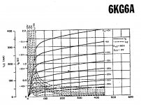
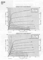
For each lower bank, use one or two 26LW6, 40KG6, or 26LX6 tubes. Some gain adjustment would be needed to match the upper and lower banks then. Screen voltage for the bottom pentode bank would be ground based, so easy to derive. Just an idea. Cheaper to do. Try on one amplifier 1st.
Optional idea:
Get a 4:1 OT to put between the amplifier and speaker. This could be just an industrial 480V to 120V xfmr to try it out. Would raise the tube loading from 32 Ohms to 512 Ohms. The triodes won't have enough voltage headroom to go to full power at 512 Ohms however. Going to 6LW6 etc top and bottom would bring back the full power rating.
Just tossin' an idea out here: You are apparently short of 12B4 tubes to fill all the sockets, and buying new ones would require 60 new matched ones.
You could use all the tubes you already have to form the upper banks of each amplifier (after testing the tubes). This could even be re-configured to use the FULL 30 sockets for each upper bank. One could also use every other socket then to double the inter-tube spacing.
For each lower bank, use one or two 26LW6, 40KG6, or 26LX6 tubes. Some gain adjustment would be needed to match the upper and lower banks then. Screen voltage for the bottom pentode bank would be ground based, so easy to derive. Just an idea. Cheaper to do. Try on one amplifier 1st.
Optional idea:
Get a 4:1 OT to put between the amplifier and speaker. This could be just an industrial 480V to 120V xfmr to try it out. Would raise the tube loading from 32 Ohms to 512 Ohms. The triodes won't have enough voltage headroom to go to full power at 512 Ohms however. Going to 6LW6 etc top and bottom would bring back the full power rating.
Attachments
Last edited:
- Status
- This old topic is closed. If you want to reopen this topic, contact a moderator using the "Report Post" button.
- Home
- Amplifiers
- Tubes / Valves
- Killer OTLs