Afternoon all,
Some of you may have been following (or perhaps avoiding ) my attempts to design and build a SET amp:
Designing a Single-Ended Triode EL34 Power Amp
a project I've shelved for the time being.
Instead, I started a new project building an amp using pentode strapped EL84's and an ECC81 driver. Limited cashflow (and know how) forced the supsension of the previous project, so this one has been done on a strict budget, mainly from spares scavenged from the parts drawer and the darkest recesses of my workshop, where there be spiders...
The only significant outlay was £100 on a pair of Hammond 135ESE's and half as much again in sundries, which represents a considerable saving when compared to the previous project.
I applied power for the first time this afternoon, and was more than a little surprised that not only did it refrain from instantaneous and catastrophic self destruction but also passed a signal remarkably quietly.
Whilst there's still plenty of time for something to go wrong, I'm cautiously optimistic.
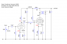
Circuit below, with measured voltages:

I scavenged the mains transformer from an old guitar amp, using a pair of diodes into an EZ81 for hybrid rectification. I've currently tapped the 190V secondary, but may brave it and switch to the 275V winding, although I may have to shuffle things around a little to get the voltages correct.
I'm playing it through my old Mission 752 Freedom speakers, which I'm aware are far from an ideal choice, but it's what I'm stuck with.
Predicatably, the mid-range is more than a little strident (listening to Kraftwerks 'Neon Lights', my wife described the upper register synth sounds as 'lemon for the ears' ).
).
Any suggestions on ways to tame the mid range would be most welcome. Before I started this whole project, I took the time to post a thread in the speaker forum, where the consensus was that this would happen, so I know I'll need to refine the response of the speakers (the phrase 'you can't polish a t**d' springs to mind).
Is there anything in the circuit I can change to even things out? There's currently no negative feedback, so presumably that could help?
As usual, all suggestions are welcome, and feel free to tell me I'm an idiot for trying. It won't be the first time, or I suspect the last...
Matt.
Some of you may have been following (or perhaps avoiding
Designing a Single-Ended Triode EL34 Power Amp
a project I've shelved for the time being.
Instead, I started a new project building an amp using pentode strapped EL84's and an ECC81 driver. Limited cashflow (and know how) forced the supsension of the previous project, so this one has been done on a strict budget, mainly from spares scavenged from the parts drawer and the darkest recesses of my workshop, where there be spiders...
The only significant outlay was £100 on a pair of Hammond 135ESE's and half as much again in sundries, which represents a considerable saving when compared to the previous project.
I applied power for the first time this afternoon, and was more than a little surprised that not only did it refrain from instantaneous and catastrophic self destruction but also passed a signal remarkably quietly.
Whilst there's still plenty of time for something to go wrong, I'm cautiously optimistic.
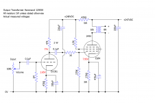
Circuit below, with measured voltages:

I scavenged the mains transformer from an old guitar amp, using a pair of diodes into an EZ81 for hybrid rectification. I've currently tapped the 190V secondary, but may brave it and switch to the 275V winding, although I may have to shuffle things around a little to get the voltages correct.
I'm playing it through my old Mission 752 Freedom speakers, which I'm aware are far from an ideal choice, but it's what I'm stuck with.
Predicatably, the mid-range is more than a little strident (listening to Kraftwerks 'Neon Lights', my wife described the upper register synth sounds as 'lemon for the ears'
Any suggestions on ways to tame the mid range would be most welcome. Before I started this whole project, I took the time to post a thread in the speaker forum, where the consensus was that this would happen, so I know I'll need to refine the response of the speakers (the phrase 'you can't polish a t**d' springs to mind).
Is there anything in the circuit I can change to even things out? There's currently no negative feedback, so presumably that could help?
As usual, all suggestions are welcome, and feel free to tell me I'm an idiot for trying. It won't be the first time, or I suspect the last...
Matt.
Last edited:
off the top of my head:
Regulate the EL84 screens and the front end
negative feedback, which will cost you some gain.
more advanced? a pentode driver with plate-to-plate feedback
As an aside I've always wanted to build an EL84 SE amplifier using an EL84 driver, ie an EL84 being driven by another EL84.
Regulate the EL84 screens and the front end
negative feedback, which will cost you some gain.
more advanced? a pentode driver with plate-to-plate feedback
As an aside I've always wanted to build an EL84 SE amplifier using an EL84 driver, ie an EL84 being driven by another EL84.
I agree with KStagger.
What you do not like about the sound is probably because of the pentode output stage operating without feedback.
I would switch to an ECC81/12AT7 for the driver and apply Plate to Grid feedback. The 12AT7 will provide the additional gain that you need so you can apply the feedback.
Steve
What you do not like about the sound is probably because of the pentode output stage operating without feedback.
I would switch to an ECC81/12AT7 for the driver and apply Plate to Grid feedback. The 12AT7 will provide the additional gain that you need so you can apply the feedback.
Steve
I agree with KStagger.
What you do not like about the sound is probably because of the pentode output stage operating without feedback.
Thanks.
I'm a little hazy as to how negative feedback actually works, and exactly I should implement it. I'll have a re-read of Morgan Jones and see if I can get my head around it.
Do I need global or local feedback, or both? Looking at other circuits, global feedback seems to take the form of a resistor and capacitor in parallel, connected between the output transformer and the cathode of the input valve. Are there any combinations which work in most situations, or will I need to calculate the component values specifically for this circuit?
I would switch to an ECC81/12AT7 for the driver and apply Plate to Grid feedback. The 12AT7 will provide the additional gain that you need so you can apply the feedback.
Steve
Actually, I'm one step ahead of you there. Looking back at my loadlines, I did in fact design the circuit for an ECC81, but somewhere along the way I convinced myself I was using an ECC82, to the point where there's actually one plugged in right now
Naturally, a check through the parts drawer reveals no ECC81's, so that's one thing to sort out tomorrow. I'm surprised the two are so interchangeable, given the ECC82's relatively low mu.
Logically, you'd expect the ECC81 to have a lower mu than the ECC82, with the ECC83 being hgher again (which is probably what confused me), but that would make things too simple
Matt.
off the top of my head:
Regulate the EL84 screens and the front end
negative feedback, which will cost you some gain.
Thanks,
Regulation seems to come up a lot here, but it's not something I've tried, or indeed know much about. Is there a simple way of achieving it without too much extra circuitry?
Matt.
If you want to try local feedback look at RH84 designs. Connect a 100-150k resistor from the plate of the EL84 to the plate of the 12AT7.
If you have an oscilloscope you could use a potentiometer to find the resistor value that achieves your goal. And then replace it with a 2Watt resistor of the same value.
I followed your EL34 SE thread. I purchased a used BEZ 6SL7 EL34 SE amp on the cheap because the owner did not like the sound quality. It was probably a factory wiring error because the tube was biased very low and distorted heavily after 1 watt output.
I changed the cathode resistor and that upped the power output and improved the sound.
However, the amp was pentode wired without any feedback. I calculated that I should use ~300k for the local feedback resistor. I put in a 500k pot and adjusted it while I watched the result on my scope and 270-350k range looked best. I installed 3 100k 2watt resistors in series per channel. The amp sounds excellent and is a keeper.
That is the easiest thing to try first.
This type of local feedback will clean up the pentode but not the output transformer. You need global feedback from one of the output transformer windings to do that. I can't advise how to do that but, perhaps another AK member will
Steve
P.S. If you decide to revisit your EL34 plans let me know and I will post the working schematic.
100-150K is quite low, I would start with the conservative 470K and work it towards but not less than 220K.
With 10K load you do not need the GNFB to fix the OPT, to my ear the GNFB always makes the amp sounding dull.
Adding the el cap to 84's G2 will make it operating better though not as good as with being regulated. The UL would be better alternative, does OPT have the UL tap?
What you probably need more is the proven schematics, with both stages' operating points selected deliberately to mutually cancel the distortions. The B+ will matter in such.
Thanks Shef. I did not pay attention to how far he deviated on OT impedance and other factors from the RH84 design.
I did say that I calculated the effective impedances for the SRPP 6SN7 EL34 design and computed that a 300k feed back resistor was in range. And then wired in a 500k potentionmeter and watched the results on my oscilloscope.
After you do the calculations that is still my recommendation for the next step.
Steve
Full pentode mode without loop NFB of some type = inadequate damping factor. Low damping factor = poor voice coil control = crappy sound. 

JMO, the distortion spectrum of the 12AT7/ECC81 makes it good driver of PP "finals", but OTT with SE. The 12AV7/5965 or (perhaps) 6GK5 would be "better".
The Hammond 125ESE is very marginal. It's not a HIFI piece, but a "universal" replacement for old radios and TV sets. In this case, no GNFB makes sense, as the core will likely saturate.

A few quick and easy things to try:
1. Up the B+ to as much as 300V.
Can also reduce the EL34 cathode resistor to 220 Ohms for a little more current.
2. The ECC82 plate is starved for voltage at only 77V. Can try reducing the ECC82 plate resistor from 47k to either 39k or 33k Ohms.
3. Less power but more damping factor, and smoother frequency response
across the low, mid, and high frequencies when driving a loudspeaker: Remove the 1.5k Ohm EL84 screen resistor, and connect the EL84 screen to the plate through a 100 Ohm resistor. (Triode Mode).
And distortion at the lower power will be less than the same power in pentode mode.
The RH amplifier ideas listed in earlier posts in this thread are good too. But it will take more changes than in 1. 2. and 3. above.
It may be more of a task to apply global negative feedback properly (make it stable).
Last edited:
If you want to try local feedback look at RH84 designs. Connect a 100-150k resistor from the plate of the EL84 to the plate of the 12AT7.
Hi Steve,
Thanks for the advice.
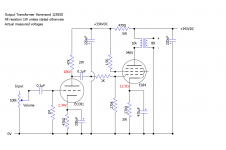
First up, my schem with the value of the driver valve corrected:

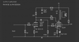
Is this is the RH84 design you're referring to:

I haven't seen feedback from anode to anode like this before, but it has the disinct advantage of being easy to implement so I'll give it a go, perhaps using shef's suggestion of starting at 470k and walking it down. I don't own an oscilloscope (although it's becoming increasingly obvious that I'll need to get one sooner rather than later), so I'll have to judge it by ear. Not something I've tried before but it should be fun, maybe a bit like tuning the soundboard on a guitar
Matt.
P.S. If you decide to revisit your EL34 plans let me know and I will post the working schematic.
I suspect my EL34 project is shelved indefinitely, but not permanently. I'll give you a heads up when I re-start. Better get this one working first!
Last edited:
Thanks for the response, I'll try the anode to anode feedback from the RH84 design and see how I get on with that.
The 'el cap' - I'm afraid you've lost me there!
Unfortunately not.
I've designed the circuit myself, so there are no proven schematics. The one above is all we have to go on.
Interesting how similar it is compared to the RH84 design, although perhaps not that surprising given the comparative simplicity of the circuits.
I suspect the main difference is that the chap who designed the RH84 circuit knew what he was doing . Seems like he had a slightly controversial presence, one wonders what you have to do around here to get yourself banned!
I'll up the B+ before I go any further, see how that affects things.
Thanks again,
Matt.
Adding the el cap to 84's G2 will make it operating better though not as good as with being regulated.
The 'el cap' - I'm afraid you've lost me there!
The UL would be better alternative, does OPT have the UL tap?
Unfortunately not.
What you probably need more is the proven schematics, with both stages' operating points selected deliberately to mutually cancel the distortions. The B+ will matter in such.
I've designed the circuit myself, so there are no proven schematics. The one above is all we have to go on.
Interesting how similar it is compared to the RH84 design, although perhaps not that surprising given the comparative simplicity of the circuits.
I suspect the main difference is that the chap who designed the RH84 circuit knew what he was doing
I'll up the B+ before I go any further, see how that affects things.
Thanks again,
Matt.
Thanks for the advice. As mentioned above, I'll up the B+ before I proceed. Also, the ECC82 was a typo, it's an ECC81. I've posted the corrected schematic above.
Will switching to triode mode not drastically reduce the power output? Or blow something up?
I've calculated output at 3.26W, but the datasheet states 1.95W max for triode connection. That doesn't sound like a good fit, unless I'm missing something?
Matt.
A few quick and easy things to try:
3. Less power but more damping factor, and smoother frequency response
across the low, mid, and high frequencies when driving a loudspeaker: Remove the 1.5k Ohm EL84 screen resistor, and connect the EL84 screen to the plate through a 100 Ohm resistor. (Triode Mode).
And distortion at the lower power will be less than the same power in pentode mode.
Will switching to triode mode not drastically reduce the power output? Or blow something up?
I've calculated output at 3.26W, but the datasheet states 1.95W max for triode connection. That doesn't sound like a good fit, unless I'm missing something?
Matt.
Progress...
Morning all,
I've spent an hour or so tinkering this morning. I've upped the B+ as suggested, here's the schematic with the measured voltages:

Checking the parts drawer, I've no high value resistors at 2W or above. I (briefly) auditioned 1W 470ok resistors anode to anode, keeping the volume low, but didn't want to push my luck.
It had a marked difference. I lost some volume, but the mid range was definitely tamed somewhat. I was listening through an appalingly trashy pair of speakers form a midi hi-fi I rescued from a skip (handily 8ohm and entirely disposable ), so I won't form any firm opinions just yet.
Suffice to say I'll order a selection of 2W resistors and audition them through my actual speakers when they arrive.
Matt.
Morning all,
I've spent an hour or so tinkering this morning. I've upped the B+ as suggested, here's the schematic with the measured voltages:

Checking the parts drawer, I've no high value resistors at 2W or above. I (briefly) auditioned 1W 470ok resistors anode to anode, keeping the volume low, but didn't want to push my luck.
It had a marked difference. I lost some volume, but the mid range was definitely tamed somewhat. I was listening through an appalingly trashy pair of speakers form a midi hi-fi I rescued from a skip (handily 8ohm and entirely disposable
Suffice to say I'll order a selection of 2W resistors and audition them through my actual speakers when they arrive.
Matt.
Your amplifier's performance is at present, with pentode connected output stage and no negative feedback, similar to a low cost tube radio output stage from 1950's.
What do you want to achieve ? Real performance (low THD, flat frequency response, high S/N etc.) or just something that pleases your ears.
What do you want to achieve ? Real performance (low THD, flat frequency response, high S/N etc.) or just something that pleases your ears.
Your amplifier's performance is at present, with pentode connected output stage and no negative feedback, similar to a low cost tube radio output stage from 1950's.
You say that like it's a bad thing
What do you want to achieve? Real performance (low THD, flat frequency response, high S/N etc.) or just something that pleases your ears.
I'm firmly in the latter camp at present. I'll leave real performance to people who know what they're doing...
Seriously though, I'm not out to set any records here. It's my first valve stereo project, I'm just out to learn a little more and have a little fun. Hopefully I'll have a working amp at the end of it, which pleases my ears.
As an aside, I've owned a couple of 'decent' amps over the years, but my favourite of all was an old Philips valve amp.
High end it was not, but it's controls were rather charmingly labelled 'Voluum', 'Hoog' and 'Laag' (if memory serves), and it made the Abbey Road sound fantastic.
Matt.
I'm firmly in the latter camp at present. I'll leave real performance to people who know what they're doing...
You have got suggestions how to improve the circuit, but it still remains basically the same. I don't see any suggested modifications applied.
You have got suggestions how to improve the circuit, but it still remains basically the same. I don't see any suggested modifications applied.
True.
As I mentioned earlier I don't have any 2W resistors of the correct value for the anode to anode negative feeedback, which is the mod I'm intending to try first.
I ordered some yesterday but I don't expect they'll arrive until the new year.
The updated schematic was just to show the new voltages with the increased B+, as previous posters had remarked it was on the low side.
Any suggestions for potential improvements?
Matt.
- Home
- Amplifiers
- Tubes / Valves
- Advice on refining SE EL84 pentode Amp