3.5 A of DC requires a filament transformer secondary of about 7 Amps.
Otherwise, transient Isquared x Rsecondary integrals will get you Hot secondary wires.
The transformer is 6.3V @ 5A so I guess I'll just have to stick with AC into the filament heaters. Thanks, thought the DC converter would minimize noise and hum. Not sure what I^2 or R secondary integrals are.
Traces look very undersized for the currents that will flow, the copper is free. 
There also appears to a mistake in the capacitor and rectifier connections (trace between D2 cathode and C2 GND)
I would GND the heat sink and use a silpad + stepped washer to secure it to the large (I hope) heat sink.
Make sure the ripple current rating of those caps is adequate. (I'm guessing north of 6A)
The transformer is 6.3V @ 5A so I guess I'll just have to stick with AC into the filament heaters. Thanks, thought the DC converter would minimize noise and hum. Not sure what I^2 or R secondary integrals are.
You could just heat the driver and pre-driver tubes with regulated DC, I used to do this quite a lot. Now I use DHTs and must use regulated, well filtered DC on their filaments, interestingly I use balanced, elevated 6.3VAC to heat the filaments of the driver tubes in these amps and have no hum problems.
On that last bit he is talking about the heat generated in the winding during the short time each cycle very large secondary current flows to recharge your caps. It generates a surprising amount of umm, heat..
a good derating of traffos is fine, for example, you need 20 va for filaments, then i will select a traffo good for 50 va at least......and forget about it...
true, the current waveforms such as with "rectification" is very much different than if it were just a plain resistive loading....so a lot of leeway is needed due to the current distortions in rectified supplies...
heating in traffo windings is a natural event, get used to it, you can however mitigate it by careful selection of traffos...
I gave a rather conservative number for the amp rating of the transformer versus the DC current needed.
It depends on the nature of the rectifier and filter.
Full wave with center tap, bridge, half wave, etc.
Cap input filter, choke input filter, and no filter (no filter does not work for Hi Fi)
I am attaching a document that shows the proper numbers.
Be sure to pick the correct circuit when you calculate.
Example, a bridge rectifier with a capacitor input filter, the formula is: I DC = 0.6 X Sec I AC
That means for a 1 Amp AC rated filament winding, you can safely get 0.62 Amps DC.
So if you need 6.2 Amps DC, you need a 10 Amp AC filament rating.
Attachments
Last edited:
I just completed an EL84 based PP amp with 12ax7 front end. I used 12.6vdc on the 12ax7 and 6.3ac for the output tubes. I ended up with a few hundred uv of hum when the volume control is turned way up and pretty much can’t hear anything right at the speaker with the volume turned down. IME hum is more likely to be the result of transformer or power supply filter current induction then filament related. You need to be careful with component and wiring layout and of course chassis and audio grounding.
For instance about 20yrs ago I built a PPPkt88 amp with ac filaments and regulated HV and bias. I had 2 toroids for HV and filaments and an EI transformer for bias. This beast weighed about 120lbs and took me months to build. I ran all the filament wiring through shields and hoped for the best. The hum was low, less than 1mv, but that wasn’t good enough for my new toy. So I went to work and built in a 12.6v 8amp filament regulator(I was running the output tube filaments in series pairs for 12.6v) Big heatsink, big capacitors etc. Result was ... the same amount of hum! Turns out that the EI bias transformer was the culprit. I managed to move it and reduce the hum to a level where it is not an issue.
Another time I built an SE headphone amp with a ecc88 and EL84 outputs, similar to a Bottlehead Crack. I thought I would try ac filaments. I carefully laid out all the wiring and parts and to my surprise- absolutely 0 hum on headphones. So, it can be done if you plan carefully and have enough space to limit PS related hum from getting into the input of the amp.
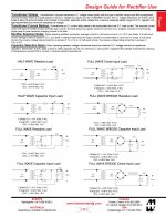
For those who still want DC heating and like experimenting, here a circuit I think could work.
First with a P-fet, but the properties are very unreliable (wide spread) so a second version with BJT+R+LED.
More current could be possible (up to 5A) with bigger 10mF capacitor and stronger rectifiers.
The MOSFET has to be a logic-in type because of the low voltage.
Before anyone asks, I can't build anything myself no more, just drawing.
Mona
Attachments
You can get a 20VA 8V 2.5A toroid for about €14 those are ideal for running 6.3VDC for some preamp tubes, no need to bother with voltage doublers.
If you have multiple 6V3 such as is the case on Tektronix iron you can put two in series and use full wave rectification with two skottkey diodes. And use something like a LD1085 for the regulator. that will give you 6VDC minimum and 6.3VDC depending on mains voltage and mains tap used on that particular iron.
I have a regulator designed for directly heated tubes that can run at a dropout of about 800mV @2.5A this could also be used for indirectly heated tubes. One plus is that its essentially a current source positioned between the + and the low side supply, and the current during startup is limited by a zener at the input of the current source.
There are all sorts of practical reasons: regulators are easily available and everyone has a bunch at hand, while not necessarily power resistors; with resistors you will always need to adjust the value, probably by using resistors in parallel; a single regulator can easily supply power to a bunch of valves, limited only by the current rating, while the RC thingie is not nearly as easy
I would have found more perplexing that not even one person in a thread like this wants to know how RC, LC, voltage and current regulation sounds on the heaters but after so many years i am beginning to accept that practically no one on this forum actually listens
I would have found more perplexing that not even one person in a thread like this wants to know how RC, LC, voltage and current regulation sounds on the heaters but after so many years i am beginning to accept that practically no one on this forum actually listens
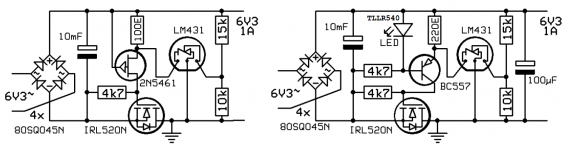
This is something i just sketched up as a LDO replacement. I have not simulated or measured the circuit but it could work as a simple regulator to provide about 6.2VDC at up to several amps at a dropout as low as the VCEsat of the transistor in question: about 200mV. Which would make 6.2VDC from 6.3VAC possible with some serious skottkeys.
Attachments
That's no good, is positive feedback.This is something i just sketched up as a LDO replacement. I have not simulated or measured the circuit but it could work as a simple regulator to provide about 6.2VDC at up to several amps at a dropout as low as the VCEsat of the transistor in question: about 200mV. Which would make 6.2VDC from 6.3VAC possible with some serious skottkeys.
You get emitter-base (driving PNP)-zener-saturated pass-transistor over the input.
Mona
[Post 30 - Ketje's mosfet based regulator] Clever design, I think the second one could work very well. My only suggestion would be to add a 100 ohm stopper resistor right at the gate of the mosfet.
Be sure to choose a mosfet that has an SOA that permits operation with at least 2V VDS at the load current. (Hint some 100A switching mosfets may not do it.)
Be sure to choose a mosfet that has an SOA that permits operation with at least 2V VDS at the load current. (Hint some 100A switching mosfets may not do it.)
There are all sorts of practical reasons: regulators are easily available and everyone has a bunch at hand, while not necessarily power resistors; with resistors you will always need to adjust the value, probably by using resistors in parallel; a single regulator can easily supply power to a bunch of valves, limited only by the current rating, while the RC thingie is not nearly as easy
I would have found more perplexing that not even one person in a thread like this wants to know how RC, LC, voltage and current regulation sounds on the heaters but after so many years i am beginning to accept that practically no one on this forum actually listens
I think you are selling us all short!! I do listen, but have never found the time to listen to different filament power configurations. My instinct is that providing you have no leakage issues between cathodes and heaters, the differences will be pretty small, and probably far smaller than many other more immediate considerations such as getting hum minimized, operating points optimized, power output adequate for the load etc.
[Post 30 - Ketje's mosfet based regulator] Clever design, I think the second one could work very well. My only suggestion would be to add a 100 ohm stopper resistor right at the gate of the mosfet.
Be sure to choose a mosfet that has an SOA that permits operation with at least 2V VDS at the load current. (Hint some 100A switching mosfets may not do it.)
I think the RFP12N10L might be a good fit for that circuit.
I still have a load of KC811 dual NPN tranistors and im thinking of modifying that circuit with a transistor Long tailed pair.
Edit i took another look at mona's circuit, the one on the right is supposed to be a current source that drives the FET gate. if im correct the TL431 functions to decrease the drive to the transistor once the voltage at the reference pin reaches 2.495V. I would include a speed up capacitor over the top resistor of the TL431 divider string, something in the order of 22uF Tantalum.
To increase the drive to the FET i would possibly add a totem pole to the fet driver circuit. or add another LED and transistor on the bottom side. to create two current sources, the top one conducting approx 2x the current where half of this current is taken away by the TL431.
Last edited:
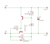
Heres my take on that circuit, i added a NPN emitter folower for lower Zout drive to the transistor. And a speedup cap for the TL431, the latter not being really needed but it gives some effect at HF at very little cost. A tantalum is reccomended in this position due to low leakage, or a 10uF film cap.
Furthermore a 1n4148 protects the PNP against reverse biasing by action of the 431.
Edit the posted circuit has an error, the resistor at the base of the NPN should be >=1K
If mona is okay with it, i can order some boards in my next order. The 2SC6144 is pin compatible with most N-mosfets GDS versus BCE so we could try both.
Attachments

Last edited:
- Home
- Amplifiers
- Tubes / Valves
- Tube heater voltage regulator