A couple more crude gm sums, down to class B.
Class aB not looking too good for grid 1 drive. (not much flat gm region in the middle for the low overlap cases)
I hope Crazy/Twin Drive fixes this mess.
Have to get my gm "scope" rigged up for real tests. Really need to know what output scheme can get the most constant gm at what bias current (or % overlap). Pentode, Triode, UL, g2 drive, g2 g1 dual drive, g2 g1 Twin/Crazy Drive...
Attachments
Last edited:
Have to get my gm "scope" rigged up for real tests. Really need to know what output scheme can get the most constant gm at what bias current (or % overlap). Pentode, Triode, UL, g2 drive, g2 g1 dual drive, g2 g1 Twin/Crazy Drive...
AB2, g1 with nested feedback to it.

gm doubling it is only one problem. I prefer to solve all problems in complex.
RE: SpreadSpectrum
That's interesting.
Any chance one could combine a humped up with a valley down set to get near constant gm? (4 tubes then)
RE: Wavebourn
I've been thinking of a transitional local N feedback inside global N feedback. The feedback transitions from global to local mode at HF.
That's interesting.
Any chance one could combine a humped up with a valley down set to get near constant gm? (4 tubes then)
RE: Wavebourn
AB2, g1 with nested feedback
I've been thinking of a transitional local N feedback inside global N feedback. The feedback transitions from global to local mode at HF.
Last edited:
I like the Audio Note kit 4 setup: A floating paraphase inverter with a small capacitor accross the anode resistor and feedback to the cathode. (controlled rolloff of HF, depending on value of the bypass capacitor about 2.5dB down at 20kHz - 11dB feedback at 50Hz, 3dB at 20kHz). Also make the PI balance adjustable and then adjust at the output after temporary disconnecting the feedback. That takes care of matching discrepancies in the following tubes and it is surprising how much difference it can make in overall distortion. (Matching is far from perfect). I do not like fixed bias and shared cathode bias resistors. Use individual bias resistors for the finals and when power output increases then the bias changes more into class AB. (6V6: 18.5 V bias at idle, 22.3V bias at full output). Even better is to make the resistors adjustable and adjust by measuring the anode current (which is as simple as measuring the voltage drop across the primary of the OPT) and not the cathode current (screen current can vary a lot from tube to tube). Just my opinion, ymmv. Peace, AM.
Last edited:
Hmmm, screen current variation between tubes would make those automatic biasing circuit boards (Tent Labs or Audiamp.eu), which use cathode sense resistors, go out of balance for the OT.
The transitional N Fdbk approach preserves the feedback correction at HF by going to local N Fdbk instead. Just rolling off all the N Fdbk at HF means no error correction there.
(controlled rolloff of HF
The transitional N Fdbk approach preserves the feedback correction at HF by going to local N Fdbk instead. Just rolling off all the N Fdbk at HF means no error correction there.
Last edited:
This "transitional feedback" is nothing good; it is a dominant pole compensation, a necessary evil when using high loop gain feedback over more than 2 stages with transformer. Nothing is good in lower feedback on the upper frequency. It is how the majority of modern solid state amps are made. When you analyze misbehaviour of different stages in extreme conditions, you would see what I mean. Input stages with weak tubes like 12AX7 are getting overloaded by high frequencies riding on the waveform of an orchestra, and as the result you hear a porridge of sounds instead of distinct instruments.
Hmmm, screen current variation between tubes would make those automatic biasing circuit boards (Tent Labs or Audiamp.eu), which use cathode sense resistors, go out of balance for the OT.....
Tetrodes have more screen current variation than pentodes. I do not like pentodes in PP due to the differences in harmonic content: tetrodes have more 2nd than 3rd and with pentodes it is the other way round. In PP the second harmonic gets minimized.
This "transitional feedback" is nothing good; it is a dominant pole compensation, a necessary evil when using high loop gain feedback over more than 2 stages with transformer. Nothing is good in lower feedback on the upper frequency. It is how the majority of modern solid state amps are made. When you analyze misbehaviour of different stages in extreme conditions, you would see what I mean. Input stages with weak tubes like 12AX7 are getting overloaded by high frequencies riding on the waveform of an orchestra, and as the result you hear a porridge of sounds instead of distinct instruments.
Let's agree to disagree - if the 12AX7 is used properly then it does its job properly. Unfortunately many belief in "less is more" and try to work with less stages rather than have each stage working in its optimum range and hence work with less overall distortion. The 12AX7 is a small signal triode and is driving a 6SN7 which is about the most linear triode around. As such mot much is required from the 12AX7.
Speaker impedance swings are the biggest at low frequencies and that is where you want the most feedback. Peace.
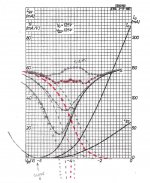
I think I'm seeing something interesting. We need a bumped up gm sum to combine with the valley'd down gm sum of class AB. Under biasing (the -3V 50 mA) can produce a bump, but will make more heat than typical class A.
The solution -may- be to use a class AB stage with a CCS tail (combined with the non-CCS class AB valley stage, so 2 + 2 tubes). The E55L CCS tailed gm curve is shown below (gm versus current). This should make nice bumped up gm sums at reduced current. Can we find a -fit- between the bumped up sum curves obtainable and the valley'd down sum curves obtainable?
Edit:
Looks like the canceling process will still leave two valleys to either side of the flattened center section. Now what to do?
Attachments
Last edited:
Broskie has a bunch of blog posts about non-gm doubling, e.g., Constant-gm Output stages part two
A little more playing with the 4 tube (2 grounded cathode in class AB, 2 CCS tail in class A) class AB stage shows that the bump and the valley can be tuned to cancel by adjusting their widths equal (by biasing V's) and by adjusting magnitude (by CCS current setting). This no longer leaves two valleys outside the central flat section, very good. But.... the gm curves outside the central flat section are increasing rapidly and winging out into saturation. A flat bottomed V with wings.
So the 4 tube "solution" just gets one to the flat bottom and winged out V shape gm sum (which I thought class AB grounded cathodes would already do).
Clearly there IS a BIG difference between class AB and class A. This promoted idea that one can operate in the flat gm section of class AB is utter BS!!!! (high Odd harmonics) The restrictive class A definition should be RIGIDLY adhered to.
Conclusions:
1) Class AB, grounded cathodes, absolutely sucks. Big V in the gm curve. No flat bottom as promoted. High Odd expansive harmonics.
2) Class A, CCS tail, absolutely sucks, Big bump in the gm curve. High Odd compressive harmonics.
3) Combined 2+2 tube class AB/A (grounded cathode + CCS tail pairs) gets you a flat bottomed V gm sum with winged out edges. Tolerable for small signals, but not good overall. (this is actually the real embodiment of what the class AB, restricted to class A portion, were claiming. Sorry, takes 4 tubes to get that!)
4) Broskie's non gm doubling designs are using diode/resistor limiters. This will give a sort of piecewise approximation to constant gm, but the kinks in the gm curve are going to produce high harmonics. Really prefer some kind of natural fit.
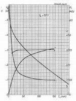
5) Twin/Crazy Drive can produce constant gm over most of its operating region (see actual Ip versus Vg graph below, slope is gm), but reverts back to essentially grid 1 operation near its cutoff end, where P-P would crossover. One would expect the gm curve to look -something- like pic 2 below. Which -could- be smoothly overlap-able. I need to take some detailed measurements (to derive gm) in this cutoff region (on the curve tracer). So that's next, some measurements. Start praying.
So the 4 tube "solution" just gets one to the flat bottom and winged out V shape gm sum (which I thought class AB grounded cathodes would already do).
Clearly there IS a BIG difference between class AB and class A. This promoted idea that one can operate in the flat gm section of class AB is utter BS!!!! (high Odd harmonics) The restrictive class A definition should be RIGIDLY adhered to.
Conclusions:
1) Class AB, grounded cathodes, absolutely sucks. Big V in the gm curve. No flat bottom as promoted. High Odd expansive harmonics.
2) Class A, CCS tail, absolutely sucks, Big bump in the gm curve. High Odd compressive harmonics.
3) Combined 2+2 tube class AB/A (grounded cathode + CCS tail pairs) gets you a flat bottomed V gm sum with winged out edges. Tolerable for small signals, but not good overall. (this is actually the real embodiment of what the class AB, restricted to class A portion, were claiming. Sorry, takes 4 tubes to get that!)
4) Broskie's non gm doubling designs are using diode/resistor limiters. This will give a sort of piecewise approximation to constant gm, but the kinks in the gm curve are going to produce high harmonics. Really prefer some kind of natural fit.
5) Twin/Crazy Drive can produce constant gm over most of its operating region (see actual Ip versus Vg graph below, slope is gm), but reverts back to essentially grid 1 operation near its cutoff end, where P-P would crossover. One would expect the gm curve to look -something- like pic 2 below. Which -could- be smoothly overlap-able. I need to take some detailed measurements (to derive gm) in this cutoff region (on the curve tracer). So that's next, some measurements. Start praying.
Attachments
Last edited:
Start praying.
Ya, I pray this stream of conciousness thread ends soon.
RE: SpreadSpectrum
That's interesting.
Any chance one could combine a humped up with a valley down set to get near constant gm? (4 tubes then)
I bet you could.
Now, I did once make a serious attempt to measure distortions caused by these variations in gm with my 30% LFB KT88 amp. I made a lot of distortion measurements at 50mA, 60mA, and 70mA bias levels. I was unable to detect differences in distortions (I measured many signal levels) at those bias levels. Both harmonic content and quantity of distortion seemed to stay about the same. It could be that my driver (CCS-loaded 6BL7) was the dominant source of distortion in the amp or it could be that the distortion caused by these variations of gm are just not that big. One thing that did change a lot with changing bias current was idle Zout of the amplifier, as expected from the change in idle gm.
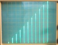
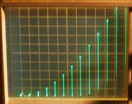
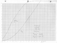
Here is a magnified section of Crazy/Twin drive (26LX6) Ip versus Vg2 near cut-off. Vertical is 10 mA/div. and steps are 2V on grid 2.
0 V on grid 2 is at the center line. So right side bar is +13V on g2 and left side dot is -11V on g2.
(takes some neg. Vg2 and Vg1 to counter the positive plate going to +370V, this is all taken on a 650 Ohm load line)
Using a bigger scale (8V steps and 50 mA/div) the Ip versus Vg2 is linear (using bigger scale) from about Vg2 = +4V up to +68V (520 mA)
From the pic it is obvious the cutoff region has a roughly parabolic shape for Ip between -11V and +4V on Vg2. Which would correspond to a linear slope of gm.
While the (earlier) bigger scale Ip plot has a constant slope from +4V (50 mA) up to +68V (520 mA) which would correspond to constant gm over most of the operating range. I'll take some detailed # measurements off the CRT to tabulate and calc the slopes for gm.
Looking good so far!
The tube hobby might be saved. Grip your chair for the final gm results....
.
Attachments
Last edited:
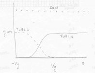
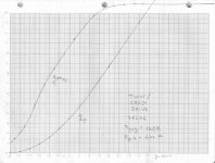
Here we go. Gm and Ip curves for the 26LX6. Rg2g1 = 10.9K Ohms, Rg1K = 622 Ohms
Table data:
Vg2.....Ip mA
-11........0
-9..........1.45
-7..........4.15
-5..........8.9
-3.........15.8
-1.........24.3
+1.........34.3
+3.........45.7
+5.........58.4
+7.........72.2
+9.........86.6
+11......101.2
+13......115.85
+15......130.55
+17......145.25
+68......520
Not a perfectly symmetrical gm S curve, but reasonable enough for overlapping. And the 1/2 max gm point is at low current, like only 20 mA idle.
I'm going to play with the Rg2g1 and Rg1K now to see if that has any big affect on the Ip curve shape. One could also play around with a small offset voltage between bottom Rg1K and the cathode. Some tubes have obviously needed a few volt offset there. Need to get a dynamic gm tester going, then I can play with the R dials.
Attachments
Last edited:
I played around with Rg2g1 and Rg1K (pots) while looking at the cut-off range Ip curves (low current), and they have large effects in this low current range. Since gm is the derivative of Ip, the effects will be significantly larger there. So there is no doubt that the shape of the gm curve can be altered. However, only a certain range of the R parameters gives the constant gm at higher currents. So this will have to be explored.
This will need a dynamic gm display to sort out what can be done for P-P crossover steady gm control. Seeing as the 1/2 max gm point occurred at only around 20 mA for the 1st test indicates that good class AB efficiency can be obtained.
This will need a dynamic gm display to sort out what can be done for P-P crossover steady gm control. Seeing as the 1/2 max gm point occurred at only around 20 mA for the 1st test indicates that good class AB efficiency can be obtained.
Nice work there SA...
So, with your constant gm zone from 20 mA onwards, it looks like there is no need to do a full overlap Class A.
Now with a full overlap design, the cut off areas would lead to a slightly decreasing gm at the extremes...flat in the middle, but turning down as we get to the 20 mA line...
cheers,
Douglas
- Status
- This old topic is closed. If you want to reopen this topic, contact a moderator using the "Report Post" button.
- Home
- Amplifiers
- Tubes / Valves
- Definition of Class A?