Fundamentally it should work.
A lot of resistor values are missing. If they are correct for the tubes that they will bias and load, OK.
The idea of negative feedback is tricky. Different output transformers, different layout,
etc. may require adjustment of the feedback circuit in order to make the amp stable into
a resistive load, and especially into the loudspeaker load that it will be used with.
I believe the only regulation is the 300B filaments, right?
I always use a series string of 2 fuses, i.e. a 2A slow blow, and a 3A fast blow
(don't get hung up on those example values).
The intent is to have a fast-blow fuse that is as small as possible, but that does not
blow during the inrush currents during turn on of the amp.
The slow-blow fuse is as small as possible but that will not blow during the warmed up
current of the amplifier.
Now the amp is double protected (against different types of amplifier faults).
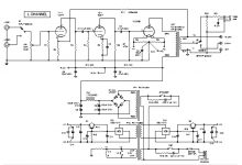
Missing alot ( values - connection VK3)Hello,
I came across this circuit and wondered what people thought before I dig in further on the design. It is a regulated 300B SE unit.
TIA
Mona
I note that the feedback loop includes the OPT which adds a laggy bandpass filter.
The bandpass effect means that even if you have a usable amount of feedback it will be less at the frequency extremes which is where you may need it. The lag affects stability as noted above.
I'd therefore recommend you add heavy feedback around the tube-only stages to give the OPT a nice clean low-impedance drive and predict this will sound much better. At least it did with the amp I tried it on, and the principles of why it did are solid.
Ignoring the tube's design limits might get you into trouble, this designThanks, guys.
This is a commercial design from a less-experienced tube amp guy.
I have other schematics from him that I will post in another thread. He is pretty inexpensive but I don't want a nightmare on my hands, either.
does ignore the 300A maximum g1 resistor. The absence of fuses will
make damages larger then necessary.
The 300B lives outside it's designed area. It still might work. But you cannotIs the circuit dangerous?
complain if the tube goes into thermal runaway.
There is no point in using the tube outside it's spec, one could easily change
the grid resistor to be within design limits.
Hello,
I came across this circuit and wondered what people thought before I dig in further on the design. It is a regulated 300B SE unit.
TIA
There are a few problems:
1) The series capacitors in the power supply need 100K equalizing resistors. The tolerances of electrolytics isn't tight, and the DC will divide unevenly. This could lead to overvoltage across one or the other in the series string.
2) There are two capacitor couplings, both with 0.1uF capacitors. That will cluster the low frequency phase shift, possibly leading to low frequency stability problems once the gNFB loop is closed. Capacitor couplings need to be staggered to prevent that.
3) The input isn't protected against DC offset. You need an input coupling capacitor unless you're certain you won't be connecting to anything that could have DC offset.
4) The spec sheet for the 300B lists 250K as the max value for a grid return resistor. Here, you have almost twice that value. This could lead to a run-away condition. That's why I'd like to see a separate grid driver. A follower eliminates that problem, as well as the heavy load on the final gain stage. Triode gain stages don't drive heavy loads gracefully without distortion.
Also, complaints about disappointing sonic performance of 300B's is almost always due to designs with inadequate grid drive. Even if you're nominally operating in Class *1, these power triodes need adequate grid drive both for Ci + CMiller, but also for grid current, as grid current will flow even though Vgk < 0V.
5) I would lose that head jack and its associated switch. A failure there could leave the secondary of the OPT without a load, and that's a disaster waiting to happen. A plate current cutoff will let the OPT free wheel like a TV HD xfmr. Unlike a TV HD coupling xfmr, the OPT wasn't designed to stand up to K-volts, and you could lose the OPT. Also, decide what your load is, and connect the gNFB loop to that point. Connecting to the top of a multi-tap secondary with only part of it connected across the load gives stability problems.
unnedded Standby switch could be eleminated.
Not for a solid state power supply. The voltage will come up very fast even before the cathodes have a chance to warm up. It's better to allow for the application of heater power, let the cathodes warm up, before turning on the HV. That's how I do designs where SS power supplies are used. You could avoid the problem if the HV supply were redesigned to use hollow state power diodes.
Last edited:
- Status
- This old topic is closed. If you want to reopen this topic, contact a moderator using the "Report Post" button.
- Home
- Amplifiers
- Tubes / Valves
- What do you think of this circuit