I am in the process of rebuilding an Akai 1710 reel to reel as a fun side project. It's not the greatest, or top of the line, but I really like this little bugger and decided to do a full overhaul on it. I have just about completed the transport section and am trying to decide on what to do with the amp.
I have the schematic for the amplifier section, but I don't fully understand all of it. I'm only familiar with tube amplifiers on a very basic level, so I'm trying to break it down into sections to make it a bit easier to wrap my head around.
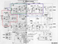
What I think I'm seeing is that in playback mode the tape head signal is fed straight to the amplifier (green section) that is using a 12AT7 valve, and that is then output to a rectifier (purple section) using a 6BM8 valve which creates the signal for the internal speakers. Is that even close to correct?
I have the schematic for the amplifier section, but I don't fully understand all of it. I'm only familiar with tube amplifiers on a very basic level, so I'm trying to break it down into sections to make it a bit easier to wrap my head around.
What I think I'm seeing is that in playback mode the tape head signal is fed straight to the amplifier (green section) that is using a 12AT7 valve, and that is then output to a rectifier (purple section) using a 6BM8 valve which creates the signal for the internal speakers. Is that even close to correct?
Attachments
Last edited:
Pretty close, except the 6BM8 is not "a rectifier" but rather a triode-pentode combo tube, which acts as the driver and the power amplifier for the internal speaker.What I think I'm seeing is that in playback mode the tape head signal is fed straight to the amplifier (green section) that is using a 12AT7 valve, and that is then output to a rectifier (purple section) using a 6BM8 valve which creates the signal for the internal speakers. Is that even close to correct?
Ok. I think I've got it.
The 12AT7 section is actually a tape head preamp that brings the head signal to line level. From there it is fed to the line level outputs and the 6BM8 section which is the actual amplifier for the internals. Correct?
If so, that would mean, hypothetically, the 6BM8 section could be completely removed if someone only wanted to feed a line level signal to an external amplifier? Or replaced with pretty much any amplifier that accepts a line level input if you wanted to keep the internals?
I'm assuming some of what I don't understand in the 12AT7 section is there to provide NAB/IEC equalization?
there is a common oscillator for record and erase heads (80 to 100khz)
the audio is fed into the record head via the 2nd tube stage switch.
1st tube stage from both channels appears to be used as oscillator when in record mode
all switches must be clean in order for this to work properly
the audio is fed into the record head via the 2nd tube stage switch.
1st tube stage from both channels appears to be used as oscillator when in record mode
all switches must be clean in order for this to work properly
Thank you for the replies. For now I'm just going to clean all of the leads and fix any solder points that look like they're getting dodgy. I'm finding that I seem to lack the fundamental foundation necessary to do any alterations to the amp circuit safely at this time. I think I need to do some more learning before I get too far ahead of myself.
My ultimate goal is to eventually update the amp. Whether that will be recreating the original design with modern parts (where possible), or trying to replace it with another tube based design, I'm not sure. I need to learn enough to know if I can even do that.
My current goal is to convert the rat's nest of wires into a PCB solution of the same design (and update the caps while I'm at it). This is something I've done before, and if I take it very slowly, one connection at a time, I should be able to achieve my goal and gain a much greater understanding of how this amp is structured.
The tape head preamp you're looking at does not have the ability to drive much in the way of cables. I would recommend not trying to get a line level signal from that point. The actual "preamp outputs" are even worse, though you could add some mosfets, caps, and resistors in there to make a source follower to make that output useful. You could get a line level signal at the speaker outputs though. Even using a TRS to RCA adapter from the headphone jack won't be a problem.If so, that would mean, hypothetically, the 6BM8 section could be completely removed if someone only wanted to feed a line level signal to an external amplifier? Or replaced with pretty much any amplifier that accepts a line level input if you wanted to keep the internals?
Yes, there is an EQ network in there.I'm assuming some of what I don't understand in the 12AT7 section is there to provide NAB/IEC equalization?
I just picked up an Akai 1700 for a similar project and am in the same boat. The amp circuit is so much more complicated than I expected to find as it is all tied into the recording circuit. I'm hoping I can figure out how to modify this to take a phono input and run it as a low watt stereo amp for horn speakers.
- Status
- This old topic is closed. If you want to reopen this topic, contact a moderator using the "Report Post" button.
- Home
- Amplifiers
- Tubes / Valves
- Help understanding Akai 1710 schematic