Hi from PEI,
First post, even though I have been a member for quite a while ...
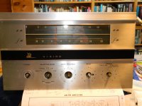
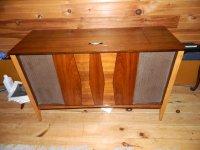
I am an old retired engineer who last built stereo (valve) amps as a young BBC engineer in the early 60's. We have a CF Eaton stereo console from ca. 1963 with Viking RCS-506, and a Collaro auto change record player..
The cabinet has been restored and revarnished, and the Viking is in good shape. The cabinet has always been indoors, and there is no rust on the chassis, and the face plate is almost unmarked.
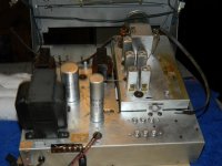
AM/FM Tuner mounted on main chassis, and amp has 5U4BG, 7025A and 6BQ5 output tubes in SE mode, but it has not seen power for over 10 years...
I have my light bulb tester ready, but have not applied any power yet. Transformer checks using DVM to look at resistance values show at least the same resistance values on secondaries either side of the center tap in the power transformer.. Long way to go yet...
To cut a long story short, my view is, that restoration means just that... Replace any component which is Kaput, or 'suspicious', recap electrolytics, paper caps. Clean and polish, check resistors, transformers, tubes, check voltages when power can safely be applied.
If I replace chunks of the circuit with a new design, then I feel that am not performing restoration, and I might as well completely gut the chassis, and use it as the home for a completely new amp...
It has all things like grid leak bias in the input stage after the volume control 1M pot. Global Negative feedback,. It designed for ceramic cartridge, so no RIAA circuits, power supply has capacitance input filters (no chokes)..etc...
That is how it was designed and built between 1961 and 1963.. I do need to bring the a.c. input up to snuff, as there is no fuse, unpolarized plug, and safety is a prime concern in this area.
Am I being overly altruistic here... Maybe it is an old man's nostalgia for a simpler unchanged world...lol..I've attached some pics of the cab and chassis.. The AM/FM dial is "real glass", and the power transformer is a serious lump of iron.....The brown stain on the tuner chassis in the second pic top right, is old glue or varnish, not rust.
Any observations on restoration vs modification...
Regards Richard
First post, even though I have been a member for quite a while ...
I am an old retired engineer who last built stereo (valve) amps as a young BBC engineer in the early 60's. We have a CF Eaton stereo console from ca. 1963 with Viking RCS-506, and a Collaro auto change record player..
The cabinet has been restored and revarnished, and the Viking is in good shape. The cabinet has always been indoors, and there is no rust on the chassis, and the face plate is almost unmarked.
AM/FM Tuner mounted on main chassis, and amp has 5U4BG, 7025A and 6BQ5 output tubes in SE mode, but it has not seen power for over 10 years...
I have my light bulb tester ready, but have not applied any power yet. Transformer checks using DVM to look at resistance values show at least the same resistance values on secondaries either side of the center tap in the power transformer.. Long way to go yet...
To cut a long story short, my view is, that restoration means just that... Replace any component which is Kaput, or 'suspicious', recap electrolytics, paper caps. Clean and polish, check resistors, transformers, tubes, check voltages when power can safely be applied.
If I replace chunks of the circuit with a new design, then I feel that am not performing restoration, and I might as well completely gut the chassis, and use it as the home for a completely new amp...
It has all things like grid leak bias in the input stage after the volume control 1M pot. Global Negative feedback,. It designed for ceramic cartridge, so no RIAA circuits, power supply has capacitance input filters (no chokes)..etc...
That is how it was designed and built between 1961 and 1963.. I do need to bring the a.c. input up to snuff, as there is no fuse, unpolarized plug, and safety is a prime concern in this area.
Am I being overly altruistic here... Maybe it is an old man's nostalgia for a simpler unchanged world...lol..I've attached some pics of the cab and chassis.. The AM/FM dial is "real glass", and the power transformer is a serious lump of iron.....The brown stain on the tuner chassis in the second pic top right, is old glue or varnish, not rust.
Any observations on restoration vs modification...
Regards Richard
Attachments
As a fellow retired electronics engineer who built his first 30Watt valve amplifier using EL34 x 2, ECC81 phase splitter, ECC83 driver and pre driver with EF86 RIAA preamp back in 1961.
I would bring the AC up through a bulb limiter, (just in case) and if OK with heaters, power off, insert the rectifier and then monitor the DC across the smoothers when powered up.
These amplifiers were built to last and if no hum, then I would assume things are good and change nothing unless there is a problem.
If it is live chassis design, ensure the power cable is polarised correctly with neutral as chassis. That was the system then and for the likes of us, see no reason to change it unless the chassis is floating and then in that case fit 3 core flex with a BS1363A plug top.
Don't let the older stuff die!
Thanks John..
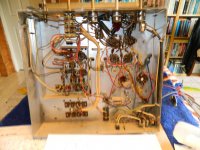
I'll let you know what happens.. It is well built, all by hand,(not a pcb in sight)...
It appears to be live chassis, but as yet I have not powered up, because my bulb limiter wasn't ready......
I also remember my first loudspeaker,which was comprised of sand sandwiched between plywood sheets (separated by 2x4 or similar pieces of wood) with a hole in the middle for the speaker. The contraption was angled across 2 walls in a corner, and voila.. infinite baffle !!!
Rgds
Richard
If I understand you correctly, you would not firstly replace the electrolytics prior to bringing up rectifier... They look to be in good shape, no rust, etc, and no obvious short circuits to ground, but is it really wise to do this, after all this time with no power on them...(at least 10 years)
My German Shepherds will not be amused if the caps go "bang...."
Rgds
Richard
My German Shepherds will not be amused if the caps go "bang...."
Rgds
Richard
Unlikely to be live chassis. It has a mains transformer and 5U4 rectifier.
If unused for 10 years or so the PSU electrolytics may need some reforming, but you may get away with letting them do this in operation. I would attach a meter to the reservoir cap and monitor the voltage. If it comes up fairly smoothly when the rectifier cathode heats up then you may be OK. However, I would keep the first 'switch on' fairly short and look out for any funny noises or funny smells. If it can keep some voltage then a second 'switch on' (still with the lamp in circuit) can be a bit longer.
The second thing to check for is leakage in the coupling cap feeding the output grid. Put a meter on the grid and check that the voltage remains near zero. If it rises than you have a leaky cap or a gassy valve. The latter may recover; the former will not.
Having checked these two items there is much less that can go badly wrong, so then you can take your time to find and fix any other faults and then deal with potential future faults.
Usually, if you power up gently and observe smell, movement and crackles, there should be no issues.
Older electrolytics tend to dry out and go open circuit due to the nature of the manufacturing process. Newer electrolytics, are packed very tightly and heat up quickly if there is a problem.
I am not saying they will all be fine but the chances of a short circuit is quite remote.
As DF96 says, keep a constant eye on them and listen for issues.
Thanks to both of you for your advice.. Much appreciated.. It has been a long time since I did any real engineering !!!! It is surprising how quickly some things come back, and how other things are lost for ever
As Bertrand Russell once remarked.."No matter how eloquently the dog barks, he cannot tell you that his master is poor, but honest"
Richard
As Bertrand Russell once remarked.."No matter how eloquently the dog barks, he cannot tell you that his master is poor, but honest"
Richard
Definitely replace the electrolytic capacitors. As was previously posted, they literally dry out over time. The modern product is much better in all depts., especially ESR and volumetric efficiency.
If you value your LPs, the Collaro/ceramic cart. combo. needs to go. A cost effective, good sounding, and physically small RIAA phono preamp is Jim Hagerman's Bugle2.
If you value your LPs, the Collaro/ceramic cart. combo. needs to go. A cost effective, good sounding, and physically small RIAA phono preamp is Jim Hagerman's Bugle2.
Don't worry, I have a separate stereo system with Linear Tracking turntable, and magnetic cartridge. My vinyl collection dates from early 70's to mid 80's. They have been very carefully looked after over the years., and are stored in Master sleeves inside the album covers. The Collaro turntable will be cleaned, and put back in the cabinet as a show piece, but it basically fills the hole it came out of..
Thanks for the advice.. For young people today who were not brought up in the vinyl age, your observation is very pertinent..
Have a good week, and regards from Atlantic Canada..
Richard
Thanks for the advice.. For young people today who were not brought up in the vinyl age, your observation is very pertinent..
Have a good week, and regards from Atlantic Canada..
Richard
I ordered replacement electrolytic caps, and replacements for the few paper caps that are in the amp a couple of days ago... I had planned to leave the old cans in place, after cutting their connections, and wiring the new caps in place under the chassis where there is plenty of room. I kept to the original values, but will be easy enough to obtain larger values (except for the input cap) at a later date if I feel it is necessary...
I will replace the caps before any power testing, as it also gives me an opportunity to check the values of the resistors in the CR filters, once I have disconnected the filter electrolytics...
Thanks for your patience folks
Regards
Richard
I will replace the caps before any power testing, as it also gives me an opportunity to check the values of the resistors in the CR filters, once I have disconnected the filter electrolytics...
Thanks for your patience folks
Regards
Richard
Don't worry, I have a separate stereo system with Linear Tracking turntable, and magnetic cartridge.
OOps...Should read moving magnet (MM) cartridge !
Unlikely to be live chassis. It has a mains transformer and 5U4 rectifier.
I recall a 1950's Philips radio (I think it was a Sagitta) that a friend of mine gave to me as I was a young boy. It featured a mains transformer, a tube set that was typical for an European AC radio set in those days: ECC85, ECH81, EF89, EABC80, EL84, and even a two way rectifier EZ80 was present. But it had a live chassis, though, as the power tranny actually was an autoformer, with the first part of it's single winding being the 6.3 V heater supply, followed by several taps for the different mains voltages, and a 250 V prolongation to which both rectifier's plates were connected in parallel.
A few years ago I myself pulled a small Grundig kitchen radio out of the dumpster. It had three E series tubes, an UCL82 AF amplifier, and also an autoformer with a live chassis and a one way selenium rectifier.
This led me to be very cautious and first make some essential measurements, before plugging any unknown device into the mains outlet.
Best regards!
- Status
- This old topic is closed. If you want to reopen this topic, contact a moderator using the "Report Post" button.
- Home
- Amplifiers
- Tubes / Valves
- Restoration of 60's Viking RCS-506 tuner/amp for CF Eaton