Yes, as I stated earlier you would use a DC feed resistor (the screen still sees the same AC source impedance as in normal UL, ignoring the resistor which is in parallel and assumed large).I suppose you are right about that, any way around it?
Last edited:
as Jazbo points out below, the down-going swing, when added to the DC screen voltage, could drop too low or even go negative. But of course, we assume you would choose a tapping point that did not go too far (this would normally qualify as distributed loading rather than ultra-linear).
It would be a 40% tap. Again, I have to wonder if the behaviour on a down-swing would be any different than the TO-350, which uses a 43% tap and does not cause any issues. Am I missing something? I'll admit I am running on very little sleep
True.Everything I have read indicates that the weakest link in ultra-linear design is the transformer and the primary winding design. In particular, inferior transformer quality can cause various issues with high frequency response.
Sorry but no, because the main problem does not lie thereIt occurred to me that a standard ultra-linear tap could be replaced with a voltage divider (resistor network) between the center tap (B+/AC Ground) and the plate supply on each output tube. Presumably one would need to use non-inductive resistors with tight tolerances. Am I wrong to think this would eliminate some of the concerns associated with the transformer design?
The real problem is the transformer as a whole, as in having proper primary inductance, low leakage inductance, low parasitic capacitance, good core linearity, lower phase shift which complicates feedback, resonances near the audio band, proper interleaving, etc. , none of which is addressed by feeding screens from a resistor divider, even if buffered.
Add to that highly variable and non linear screen current and you´ll see why:
this isn't done, or the potential complications with such a design?
Which tubes you are planning to use?
Walter
I was planning to use KT88 at normal rated voltages, but I am thinking about trying 6146 now, which is why I asked the second question.
Thanks for the reply @JMFahey. The first question was already answered, though your reply helps clarify it.
I'm still curious about the possibility of cap-coupling the UL tap, but it looks like I will be better off just using KT88s within their limits rather than trying to make 6146 work.
I'm still curious about the possibility of cap-coupling the UL tap, but it looks like I will be better off just using KT88s within their limits rather than trying to make 6146 work.
Transformers designed for UL operation generally have good coupling between the 40% sections and the secondary by design (winding proximity). But for low cost UL OTs, often at least one of the 60% sections will have poor coupling, being wound on the outermost region of the OT core without extra interleaves, and with unbalanced winding resistance. So one can get into (phase) trouble between the primary and secondary using the plates for feedback in that case. (you might be better off using the real UL taps for the R divider take-off in that case)
This problem also applies to local "Schade" Shunt Fdbk too. You can easily measure the coupling between the secondary and the different winding sections using an L meter and shorting a section. (need to compensate for the turns ratio squared of the sections for leakage L comparisons) One needs to check for leakage L balance between the pick-offs for the P-P sides, and equal winding resistance. A really good OT will use double bobbins so that both sides of the P-P will have equivalent windups and crossed interleaves as well.
A separate, balanced, N Fdbk winding (in close proximity to the secondary) can give good results (especially with the high Z Mosfet follower gates being driven) since no load current means no V drops through any leakage L in that case. But adding extra windings to the OT in general will make all the other leakage Ls get bigger. Tough decisions.
Last edited:
Diode in series with ultra-linear screen tap?
A certain Mr. Dennis R. Grimwood has some interesting comments about operation of tetrode and pentode output stages on his website.
In particular, he states here:
Further, regarding ultra-linear output stages in particular, he states:
Something about this configuration is off-putting to me, but I cannot put my finger on it. Has anyone tried it? Is there anything about it that would cause issues, in theory? Thanks!
A certain Mr. Dennis R. Grimwood has some interesting comments about operation of tetrode and pentode output stages on his website.
In particular, he states here:
By inserting a standard half-wave silicon rectifier diode in series with the Grid Stopper resistor, an electronic control circuit is created whereby the Screen Grid will be able to be energised at DC potential attracting and accelerating electrons towards the Plate - still electrostatically controlling current flow in the normal way - but blocking the flow of AC current from the Screen Grid back to the DC source - ie "one way traffic" [...] Thus then there is no output circuit formed between the Screen-grid and the load so no current can flow in the usual direction. [...] This arrangement offers huge benefits, because it prevents the Screen Grids from collecting electrons - thereby diverting all the signal output to the Plates, increasing tube efficiency, reducing distortion and increasing frequency response, as well as eliminating the usual effects [of] changes in Screen Grid voltage on Plate Current - therefore improving transient response.
Further, regarding ultra-linear output stages in particular, he states:
[This technique] is very helpful in ultra-linear connection. AC signal output voltage from the Screen-Grids is prevented from conducting through to the output transformer, which means that the ultra-linear output stage operates as a negative feedback system only - ie Plate voltage is fed back to the Screen Grids via the transformer taps but not the other way around. This method ensures all the electron flow goes to the Plates, with all the advantages described previously.
Something about this configuration is off-putting to me, but I cannot put my finger on it. Has anyone tried it? Is there anything about it that would cause issues, in theory? Thanks!
Last edited:
Mr Grimwood sounds like the slightly crazy but fun old Uncle many of us have.
Quite inoffensive, unless you start following his ideas.
No need for an external series diode since you already have one there: the screen IS an anode, relative to the cathode, and current can flow one way only, no matter what.
Quite inoffensive, unless you start following his ideas.
Not such an AC current, and definitely NO current flow from screen towards the DC supply.but blocking the flow of AC current from the Screen Grid back to the DC source - ie "one way traffic" [...]
No need for an external series diode since you already have one there: the screen IS an anode, relative to the cathode, and current can flow one way only, no matter what.
Mr Grimwood sounds like the slightly crazy but fun old Uncle many of us have.
Quite inoffensive, unless you start following his ideas.
hahaNot such an AC current, and definitely NO current flow from screen towards the DC supply.
No need for an external series diode since you already have one there: the screen IS an anode, relative to the cathode, and current can flow one way only, no matter what.
I think the idea was that it would prevent the flow of electrons absorbed by the screen to the DC supply, which is situated at AC ground (bypassed to ground with capacitor). Since the screen is an anode, it does absorb a portion of the electron stream from cathode to plate, dissipating a portion of the total current flowing in the tube. This does make some sense to me; perhaps I am misunderstanding where that current goes?
Last edited:
The AC component of screen grid current is added to a DC component that keeps the sum always positive. So putting a (conducting) diode in series does none of the things claimed, except drop 0.6V.
Besides...., getting the AC component of screen current back into the OT -IS- most helpful, just that it needs to go to the 100% plate tap instead of the UL tap for best distortion reduction.
There is one scenario where the series screen grid diode may be helpful. When the screen grid becomes overloaded sufficiently to cause the grid wires to glow (ie, from extended maximum signal output) the diode prevents the screen grid from thermionically emitting electrons to the plate when the plate swings to 2 x B+. (so preventing instant tube melt-down). No sonic benefits however, except continued operation.
The AC component of screen grid current is added to a DC component that keeps the sum always positive. So putting a (conducting) diode in series does none of the things claimed, except drop 0.6V.
That makes sense. Thanks!
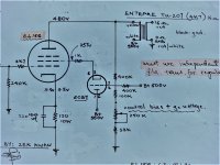
It is clearly related to UL mode, but has some differences in detail. More like what would be seen for "UL" mode with a TV Sweep tube (low Vg2 rating). The screen voltage is being kept below the plate voltage by the divider resistor chain, and the screen current is not being returned to the OT at either a UL tap or the plate tap like tapped UL. The cathode follower tube buffers the divider from screen current pulling of the divider voltage, but by using a triode for the buffer, it cannot return current to the OT due to minimum voltage limitations of the triode's operation. A Mosfet follower might be able to do that, depending on the setting ratio of the R divider.
Odd to see this for an EL156, since it has a 450V rating for Vg2. Maybe just used because the OT did not have a UL tap.
Odd to see this for an EL156, since it has a 450V rating for Vg2. Maybe just used because the OT did not have a UL tap.
re lowering screen voltage - You could use zeners in series with the UL tap -
I did this with a single-ended UL amplifier, using a 5W / 75V zener. One of the zeners did eventually short. Either I went over the max voltage or the max power dissipation. Given the tubes I was running at the time - EL156s - I just directly connected the UL tap to the screen.
I did this with a single-ended UL amplifier, using a 5W / 75V zener. One of the zeners did eventually short. Either I went over the max voltage or the max power dissipation. Given the tubes I was running at the time - EL156s - I just directly connected the UL tap to the screen.
Last edited:
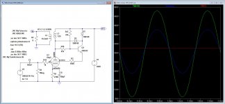
I've had similar ideas in the past when reading up on UL. What might work is to drive the screens from a low Z source such as an emitter or FET follower, then use resistive summing at the input from a DC reference for bias, and the voltage divider off the plate. Do the voltage division at a high Z point in order to not waste power. You can try to employ the DC path R as part of the voltage divider or at least account for the finite impedance there.
- Status
- This old topic is closed. If you want to reopen this topic, contact a moderator using the "Report Post" button.
- Home
- Amplifiers
- Tubes / Valves
- Alternative Ultra-Linear Connections?