Some things that I have done when delay is necessary but I don't want to stuff the chassis full of boards/parts:
1. Get a rotary switch with at least 3 positions and 2 poles. For the first position, just send power to a heater transformer to warm up your tubes. For the second position, send power to both the heater transformer and HV transformer. The last time I bought such a switch, it was about $8.
A similar arrangement was included as part of the original design.
2. Use tube rectifiers. You can get some rectifiers that take considerable time to warm up, and this will generally provide sufficient delay.
3. Do nothing. 807s are tough buggers, they aren't going to mind the stress that comes with turnon, and they frankly aren't particularly expensive to replace if you need to.
Neither of these were design considerations. If you check the schemo, there are two DC couplings: between the first preamp and the phase splitter, and between the cathode followers and the 807 grids. If you turn on the HV supply before the cathodes are warmed up, you will hit those tubes with the full HV. I don't know if 6SL7 grids will survive that. If you change to hollow state power diodes, then you'll need a PTX with higher voltage to compensate for the much greater forward voltage of the hollow state diode.
As for the grid drivers, the full negative rail voltage is way in excess of the 6SN7 VHK spec, and you're asking for a flash-over if the negative rail voltage is applied when the cathodes are cold. If the cathodes are preheated, the plates draw current as soon as the HV comes up, and you avoid these problems.
I had the same problem with another design. The solution for both designs is to float the heater power supply. In the Vixen, this was accomplished by a DC heater power supply. In the Renard, the heater secondary of the PTX was left floating. That didn't cause the hum you'd expect.
Eh, something like the Eico HF-89 was equally hard on its LTP.If you turn on the HV supply before the cathodes are warmed up, you will hit those tubes with the full HV.
Yeah, it would likely move in the wrong direction in terms of performance also.If you change to hollow state power diodes, then you'll need a PTX with higher voltage to compensate for the much greater forward voltage of the hollow state diode.
There's also that spare 6V winding in the power supply. Biasing that winding separately and using it to heat the cathode followers would keep you protect, but what a pain in the butt!As for the grid drivers, the full negative rail voltage is way in excess of the 6SN7 VHK spec, and you're asking for a flash-over if the negative rail voltage is applied when the cathodes are cold. If the cathodes are preheated, the plates draw current as soon as the HV comes up, and you avoid these problems.
The schematic shows that the DC supply is earthed.I had the same problem with another design. The solution for both designs is to float the heater power supply. In the Vixen, this was accomplished by a DC heater power supply.
(Personally I'd just use the two switches or a rotary switch, my experiences with relays switching high voltages aren't positive)
For Miles:
I think I have made an assumption on the screen regulators, 6AQ5 and 6CB6, and planned to place this in the power supply. My question is that you intended this to be a separate circuit for each channel, and not one shared between the two channels. Correct me if I am wrong please.
Tim
I think I have made an assumption on the screen regulators, 6AQ5 and 6CB6, and planned to place this in the power supply. My question is that you intended this to be a separate circuit for each channel, and not one shared between the two channels. Correct me if I am wrong please.
Tim
Miles:
If your around, I have question on the choice of the 6J5 as the pre-amp, no dispute of the choice, is a nice sounding tube, and so in my question, that basis of sound being prevalent here.
I was looking at the 6C4, 7 pin mini tube, and I know the sound of this one fairly well, which got me to pondering (dangerous thing) in how close the two might be in spec's. The biggest factor I saw was the Plate to Cathode capacitance,and the plate to Heater Capacitance, being about half the value, and the heater cathode voltage is double negative respect, and the same positive respect.
I will be using the 6J5 in the build, but I am just curious if there are other factors I am not aware of between these two?
Let me know what you think on this please
thank you
Tim
Miles:
If your around, I have question on the choice of the 6J5 as the pre-amp, no dispute of the choice, is a nice sounding tube, and so in my question, that basis of sound being prevalent here.
I was looking at the 6C4, 7 pin mini tube, and I know the sound of this one fairly well, which got me to pondering (dangerous thing) in how close the two might be in spec's. The biggest factor I saw was the Plate to Cathode capacitance,and the plate to Heater Capacitance, being about half the value, and the heater cathode voltage is double negative respect, and the same positive respect.
I will be using the 6J5 in the build, but I am just curious if there are other factors I am not aware of between these two?
Let me know what you think on this please
thank you
Tim
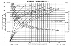
The 6C4 is an RF power triode that's most frequently used as an oscillator, Class C intermediate driver and frequency multiplier. The low capacitances are consistent with the intended usage. The u-factor graph is all over the place, and that isn't what you want to see regarding linearity for audio amplification. The 6J5 has a much more linear u-factor plot that's better for audio. The most common use for the 6C4 in audio is for cathodyne phase splitters where you have very high NFB in place to linearize the otherwise atrocious u-factor behavior.
For Miles:
I think I have made an assumption on the screen regulators, 6AQ5 and 6CB6, and planned to place this in the power supply. My question is that you intended this to be a separate circuit for each channel, and not one shared between the two channels. Correct me if I am wrong please.
Tim
The Vixen uses separate screen regulators for each channel.
Attachments
Thank you Miles, very much appreciate your thoughts, and does clarify a couple things I had in my mind. I was aware that the 6C4 is primarily for RF Oscillators such as a V.F.O. to a transmitter, and the only real reason I even considered it was because I have (Had, is in long term storage) a really nice 6L6 clone home made in 1955, that had an awesome sound, utilizing the 6C4 into a 12AU7 into the 6L6's. Since I have been out of the tube world for now for many years it is like starting all over, and that's alright, I love to learn.
Thank you for clearing up my confusion on the screen regulators, since many power supplies do use a single regulator for both channels, reading your schematic was my only indication that these need to be separate regulators, the Heaters are shown as two setts, so I am glad you cleared that up for me. I have been working on layout, and for space reasons contemplated whether or not the regulators were individual.
My update: Parts have mostly arrived, waiting on the Iron still and that will determine the final touches on the layout. I am working with all available drawings so I can be certain that nothing will change, (Laughing having experienced the drawing to manufacturing process, multiple times).
I have gotten the bench to where I can start some of the smaller things. like repair any tools/equipment needed now. Goal still set for December to begin the build.
Tim
Not much to offer as of this time, parts have begun to arrive, sorted and what not, waiting on Iron and some hardware bits actually.
Small delay on my part of indecision, whether to incorporate Printed circuits, or strictly point to point wiring. So I am laying out both possibilities before deciding.
Tim
Small delay on my part of indecision, whether to incorporate Printed circuits, or strictly point to point wiring. So I am laying out both possibilities before deciding.
Tim
Update:
I have everything now except the Iron. That should be here in the next couple of weeks, or sooner.
I tossed around the idea of placing the screen regulator on the power supply chassis, asked Miles thoughts on this, and will only be placing Transformers, inductor's, and related power supply components in the power supply, keeping the screen regulation near the screens of the outputs.
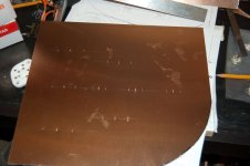
I have begun to cut chassis parts and am punching the holes for sockets.
I will get some pictures uploaded sometime this weekend.
Once I have the basic chassis together Ill start the wiring process.
I have everything now except the Iron. That should be here in the next couple of weeks, or sooner.
I tossed around the idea of placing the screen regulator on the power supply chassis, asked Miles thoughts on this, and will only be placing Transformers, inductor's, and related power supply components in the power supply, keeping the screen regulation near the screens of the outputs.
I have begun to cut chassis parts and am punching the holes for sockets.
I will get some pictures uploaded sometime this weekend.
Once I have the basic chassis together Ill start the wiring process.
Starting on the chassis
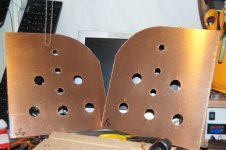
The Iron has arrived, and now I can move forward with the final touches for the chassis'. Everything will be assembled (wired) to the mid chassis and the rest of the cabinet will then become a part of the mid chassis plate. Still running ideas around on the power supply chassis and layout. Depending on the time I can find this weekend maybe I can begin to do some wiring.
I will be shooting for a longer curve than is implemented at this time, still determining materials being incorporated.
Attachments
I built a Vixen based on Miles Prower's design about 11 years ago, and it's about 95% complete, unfortunately, I received the wrong Zener diodes from the company I ordered them from, and never finished it. Also needs the coax feedback line and double checking the circuit (all the components, etc.). I used 1625's instead of 807's, and the heater voltages, etc. are correct for the 1625's. At my age now, I don't have much interest in revisiting the project, as I do have a few other amps that I built and use, so I would like to offer this for free (or if you can offer a reasonable donation) to someone who wants to take it from there, just please be able to come and pick it up in Wilkes-Barre PA (near Scranton). I'm sure it has over $400 worth of parts and iron, and the tubes are all in place as well. Someone let me know, I would rather not ship it, because of the weight, size, and fragility.
In the attached photo, it's the item at the far left.

Also, the original thread I posted about this while it was a work in progress, was this one:
Higher power amps using 807's or 1625's
If interested, send me a private message and let me know when you can come and get it.
In the attached photo, it's the item at the far left.
Also, the original thread I posted about this while it was a work in progress, was this one:
Higher power amps using 807's or 1625's
If interested, send me a private message and let me know when you can come and get it.
Last edited:
- Status
- This old topic is closed. If you want to reopen this topic, contact a moderator using the "Report Post" button.
- Home
- Amplifiers
- Tubes / Valves
- P-P 807 Build “Miles Prower's “Vixen””