While looking at other power DHT I came across the GM70, great reviews, cheap tube in huge ebay quantities. (short life at 1000 hrs tho).
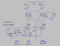
With a -110 bias @ 1020V B+ it will only run in A1.
The 4p1L at 2.5V input swings 160V pp.
In LTSpice sim at 2.5V input with the schematic attached I achieve 22Watts. Wont need over 20 ever.
Thoughts?
Have read the GM70 "'sound' <-for all that's worth" is between 300B and 211.
Easier to drive then 211?
Attachments
I've been running GM70 amps since 2011 with 1:1 interstage driven by D3A running at 20mA, with Lundahl 1:1 input transformer. Output transformer 7K primary. 1kV @ 100 - 120mA (copper or graphite plate) Fixed bias about -90V to -100V.
Happy with the result. Tube life is short.
Happy with the result. Tube life is short.
Thanks kevinkr, tube life is short due to fill req and massive power dissipation probably. I will look at some 7k OPT as well and maybe run the tube at a higher current. Doesn't look like Lundalh has a nice 7k ish OPT, some 6.5k and 9k options only. will keep looking tho.
would you say this tube is better/worse then the 211?
would you say this tube is better/worse then the 211?
Different, and more linear than the 211 at reasonable plate load resistances. I have not met too many 211 amps I liked.
I heat them using Rod Coleman CCS and average about 1200hrs of life.
I run 100 - 120W of plate dissipation, the coppers definitely should not be run much over 100W and will give slightly longer life.
I am currently running copper plates at 100mA and am up to 1500 hours now, replacement will be needed soon, but they still sound ok at the moment.
My output transformers were made by Electra-Print back in 2010, and were very reasonably priced. They perform very well, they are the only transformers outside of the PSU that have not been replaced at some point with better ones.
I've searched for hours to find a T that operates in the range I want. Looks like I will go with the Electra-Print option, most options available. Planning on a 8k:8 at 100mA. If I run the tube at Q~ 100mA/1000V and want to build some room for future tinkering would ordering the 120mA version effect sound or stick to the 100mA transformer? Its just a different gap distance but wanted to check.
I had a PM on how I plan to get a 80V swing from the 4p1l and the key is the input transformer 1:4 (bal input)(LL7903) 2.5V:10V, the 4p1l is biased at -12 and yes I would be pushing the tube all out but why not.
Checkout this post by Ale:
4P1L driver – LL7903+LL1671 tests – Bartola Valves
I had a PM on how I plan to get a 80V swing from the 4p1l and the key is the input transformer 1:4 (bal input)(LL7903) 2.5V:10V, the 4p1l is biased at -12 and yes I would be pushing the tube all out but why not.
Checkout this post by Ale:
4P1L driver – LL7903+LL1671 tests – Bartola Valves
I've been very pleased with the output transformers Electra-Print has made for me.
Note that you can run the GM70 at any dissipation within reason where the plates don't glow and tube life is not materially improved or adversely impacted.
The only thing that helps at all is to use CCS filament heating which reduces the inrush when cold and reduces the flapping that will occur at high initial inrush currents.
Running them much beyond 1200 hours is a risky proposition if one of the filament breaks and shorts to the grid or elsewhere - for this reason I replace before they actually fail. Usually the magic goes away right around the time when replacement would be advisable.
I have noticed a marked reduction in emission near the end, perhaps a 15 - 20% drop in plate current since last adjustment is a reliable indicator it is time.
Good to know kevinkr! I am excited to begin this. GM70s arrive in a week. Yes I will be using the rod coleman for filaments. I currently use it on my 26 preamp and its solid.
Did you order the 120mA ouput T version? and just run it at 100mA for copper version, 120mA for graphite?
Based on the options electra-print does: 8k, 120mA, 30watt?, 8ohm, copper.
Did you order the 120mA ouput T version? and just run it at 100mA for copper version, 120mA for graphite?
Based on the options electra-print does: 8k, 120mA, 30watt?, 8ohm, copper.
IT Coupled
Check with Monolith Magnetics.
I started out with RC coupling, changed to LC coupling and finally settled with IT coupled. I had a Hammond 1629SE which was really nice, had good bass but didn't have the detail so I ordered a custom Monlith Magnetics OPT. I could of lived with the Hammond but I just wanted something higher end. The Hammond's tend to rolloff which shows up in the modeling I did. The Monolith is an S-5 gapped for 100ma, Inductance was perfect for the GM-70, bass is not an issue. You could go with an S-15 if your running a lower voltage (900-1000) which I think would give you the best results if you don't care about going into the A2 area very much.
If you have LTSpice I could send you some schematics I experimented with.
Filament Bias vs Fixed Grid Bias with its own PSU ~-100V for GM70?
That is the question.
Originally I was going to do a 5th PSU for the bias but now I am not sure.
(1-HT 4p1l, 2-HT GM70, 3-B+ 4p1l, 4-B+ GM70)
HT psu is going to a Rod Coleman Reg.
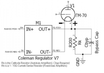
In his install documents he even has a schematic of a fulfillment bias for the GM-70, convenient (might have to adjust to proper bias V of course) image attached.
(auto vs Fixed for this size tube?)
Thoughts?
That is the question.
Originally I was going to do a 5th PSU for the bias but now I am not sure.
(1-HT 4p1l, 2-HT GM70, 3-B+ 4p1l, 4-B+ GM70)
HT psu is going to a Rod Coleman Reg.
In his install documents he even has a schematic of a fulfillment bias for the GM-70, convenient (might have to adjust to proper bias V of course) image attached.
(auto vs Fixed for this size tube?)
Thoughts?
Attachments
Last edited:
I'm running GM70 at 1kV with -90V to -95V of bias. Filament bias would result in somewhere around 270W of dissipation in the filament series resistor, plus last time I checked the Coleman regulators could not operate at 115V output.
Filament bias is a total non-starter IMO.
What is shown is what is commonly known as cathode bias which is not the same as filament bias as shown in conjunction with 4P1L, etc..
I am using Coleman regulators in my GM70 amps which have been in continuous use for about 7 years now. They need plenty of heat sink.
I totally meant to say cathode bias but have been playing so much with the 26/4p1L filament bias that I instinctively say it now without thinking. Of course never filament unless I wanna heat my house and burn Coleman regulators.
Have you ever considered a ~-90v to the secondary of the Interstage Transformer?
Are you using Fixed or Auto?
Have you ever considered a ~-90v to the secondary of the Interstage Transformer?
Are you using Fixed or Auto?
Last edited:
I have been planning the B+ PSU for the GM-70 and its not as easy as other amps Ive built. Planning on using SS diodes (tubes later years) for rectification. anyone have any recommendation?
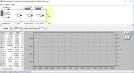
All the per-delivered ones in PSUD2 are hitting error PIV exceeded.
I plan on using the Hammond 724 (750-0-750) and Hammond 193S/Q chokes, they are rated max 1kv which is max and not sure if its ok to go a bit higher.
Higher value chokes?
Preliminary PSU image attached.
HT Rod Coleman for all tubes and their PSU were easy part.
Attachments
I used 1.6kVpiv SIC diodes in mine, in a bridge configuration with a 710V primary, more than seven years so far without issues. (They were however tested for reverse breakdown to 2kV at 65C.)
If as I suspect you are planning on using FWCT you can place diodes in series. with appropriately rated resistors and capacitors. Note also that DigiKey last time I checked still had a pretty good selection of high PIV diodes and you should look at what they have available.
I used a CLCLC filter and placed the chokes in the negative rail where they only have to stand off a few volts typically. This trick was often employed in ham gear operating at high voltages to reduce demands on choke insulation.
Don't exceed the insulation voltage rating.
I used fixed bias in the output stage and the interstage transformer is connected to the bias supply which is adjustable. I used a fair amount of film capacitance to decouple the transformer from the bias supply, the resulting time constant means I have to be careful about applying B+ before the bias is fully there. An unregulated floating bias supply using a high voltage n channel mosfet with adjustable gate voltage in the + side of the supply would be the way I would go today to provide a short time constant, low Z bias point to the transformer. LTSpice can help you figure out how to do it if it is not immediately clear. (The problem is p channel mosfets come only in drain voltage ratings of a couple of hundred V and IMO that is just not enough)
- Status
- This old topic is closed. If you want to reopen this topic, contact a moderator using the "Report Post" button.
- Home
- Amplifiers
- Tubes / Valves
- DHT amp - 4p1L driving GM70