Hello there,
As the title says, I've got a wee hum problem with an ACF-2 tube buffer I've just built, using 6SN7 tubes. Bloody things sounds really nice but the hum is killing me (what has been heard cannot be unheard).
First, I thought this was a ground loop (or an earthing issue). However, I looked at it from all angles and I don't see any loops. The chassis is tied to mains earth right at the input. The board is connected to the chassis from the house ground pad, through a little board I made myself, that has a power 10-ohm resistor and a small cap in parallel, together with 4 diodes in parallel as well (pairs of two). I've tried disconnecting the board from the chassis (leaving the chassis tied to earth), without any success.
The input/output jacks are isolated from the chassis (verified this with my multimeter) and signal grounds are paralleled all the way to the board. I have shielded part of the signal wires, but the shield is connected to signal ground only at one end.
From this, I started to suspect this is heater hum. I've measured it to be "exactly" 50Hz and I also noticed the hum goes away almost instantly after I cut power to the unit (however, some 30s after that, the power amps start to hum terribly loud - not particularly a problem as I never use them like that).
My mains transformer is a Hammond 369AX, which has a 6.3VAC secondary. It's currently wired in the Full-Wave Bridge configuration and I'm thinking the regulator doesn't have enough input voltage to output properly filtered DC, hence the noise. I am considering reworking this into the Voltage Doubler config, while keeping the reg output at 6.3V. It should dissipate a lot more voltage, but I would assume the DC should but much cleaner.
In any case, I would appreciate your input and opinions. Also, if required, I can provide some pics tomorrow
Last edited:


Yes, that’s what I built (the first schematic, with a slight difference, as the two sets of diodes are completely in paralel, not connected halfway). In any case, I tried disconnecting this, essentially doing a ground lift, without any audible difference.
I will try twisting the mains wires and shielding the output wires as well.
I’m still thinking about the heater DC filtering. If input is 6.3VAC, then raw DC should be 6,9V which seems kind of low, even for an LD reg. I can’t remember the filter cap values, but I have a strong feeling they’re 2200uF. I’ll check them tomorrow and do the math to see what ripple voltage I get. I have a very strong feeling this is where the hum is coming from.
Last edited:
I have only ever used DC heater supply once and that didn't cure the hum.
There are so many places that can generate hum.
1/ Mains transformer too close to audio/valves (50Hz)
2/ Bad grounding causing charging impulses in to smoothing capacitors to modulate the ground (100Hz)
3/ Mains wires or heater wires passing to close to audio signals.
4/ Long pcb tracks/wires on input picking up interference.
I second Nigel. The only time I've had a mains buzz on an amp that went away as soon as the power was turned off was caused by the proximity of the transformer to the tube circuitry.
I find if it's a signal grounding issue the hum persists after the power is turned off.
I use the (aluminum) chassis as signal ground with only the positive wire connecting to the grid, and the chassis as return with no hum/noise whatsoever.
I would dismount the transformer and run it through 1M+ of wire to see if moving the coil effects the hum, otherwise if it's AC heater hum connecting the heaters in series and running them from a 12V SMPS will change that variable, too.
To start with, I tried twisting both the signal wires and the trafo secondary wires. This did nothing for my hum problem, but I did manage to put the HV CT wire in the wrong position... fortunately, I only blew a supply filter cap.
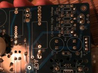
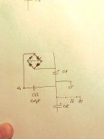
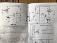
In the process of repairing it, I did notice some issues, due to the fact that the schematic is different from the actual board. If you look at the schematic in the manual, you'll notice there's the J6 jumper that connects it to house ground. However, looking at the board, I noticed there's an extra bridge rectifier (integrated, not discrete like the power supply ones) and a capacitor that weren't mentioned on the schematic. I tried to draw a new schematic, detailing what I saw on the board (you'll see that one attached as well).
From what I gather, the bridge rectifier and the cap seem to do the same job as the filter I built between the board and house ground. Therefore, I think I'll connect J6 and remove my filter. If my logic is correct, this should do the job and maybe I'll get rid of the noise (or get rid of an extra wire through the enclosure, at least)
If not... is there any way to shield the trafo? I noticed my monoblocs have small cases around both the input and output trafos, so I'm thinking that might be a solution. I'm asking because it would be rather difficult to move the trafo further back... I would have to rebuild the case.
Attachments
Hi MrJackson.
So now consider all the above advise you've been given.
Remove your mains Txformer and use extra long wires to connect to your chassis.Note what kodabmx says in #11.
What we're trying to do is exclude this as a source of hum before moving on.
PS Please ensure you have a good chassis to earth contact by scraping that black paint off to reveal the shiny metal beneath.
If you are going to use the hum solver please use it as detailed in Tubecad blog0397.
All the best and keep us informed of your progress.
I've removed my connection to house ground from the HG pad (which went through my own filter) and put a wire in place on J6. This brought a significant improvement on the HF noise I was hearing with the volume pot at mid position. Hooray to that.
Just out of curiosity, I took an aluminum pot and covered the mains transformer (and then the tubes). This made absolutely no difference in regard to the bloody hum. I know aluminum isn't the best shield, but I was expecting some change however small.
I will try to get the transformer further apart from the circuitry later today, but I would be slightly baffled if this worked, considering my power amps have the tubes right next to both input and output transformers (literally).
PS: Does it make any difference if I join the signal grounds (input and board) for one channel on the volume pot or on the board? They're currently joined on the pot.
So, updates available. I've tried the following things.
1. Assumed heater DC is not "raised" correctly. Removed C7 from the board... massive hum. Put back C7, but removed the voltage divider made by R8/R9... same low hum.
2. Assumed heater DC is not correctly regulated. It wasn't. Reg input was 6.9V, much lower than the min 7.5V needed for regulation. Changed the heater supply config to the voltage doubler one, set the reg to output 12.6V and put the heaters in series (6.3V tubes). Did it fix the hum? No. But now the tubes glow stronger and have the proper voltage (measured it). In the meantime, changed C3 from 3300uF to 4700uF... no effect.
3. Bit the bullet and removed the trafo from the enclosure top. Put in some longer wires and connected it back. And guess what... still no change. I have tried moving the wires around to see if some EM field is causing this, but without any success. No matter what I do, the hum is constant in volume and frequency,
However, I did notice there is a mechanical hum coming from the board (without any power amps connected). This is at the same 50Hz frequency. Disconnecting the B supply stops the hum, but doing some makes the power amps buzz, just as if the cable was connected to them but not the other way around (same happens if I power down the Aikido but leave the power amps running).
Also, there's something I don't understand. The design says the heater DC must be raised to a sufficient voltage so both the top and the bottom triodes "see" the same magnitude of heater to cathode voltage. This is done by the voltage divider I mentioned at the first point, between B+ and B- (having a bipolar supply). What I don't understand however is why the top resistor in the divider (R9) is of higher value than the bottom resistor (R8). This sets the ref voltage at -50V to ground and it would seem to me that it should've been the other way around.
Nevermind the last paragraph, I figured it out in the end. Silly me.
Last edited:
Funny thing, I read that last night. However, it's slightly different in my case (or I didn't understand what he said)... removing the house ground connection on J6 didn't get rid of the hum, but it did add a significant noise with the volume pot mid way.
As far as I understood, he got rid of the hum by lifting the ground. However, it's not entirely clear to me what he meant about fault conditions. My case is still tied to house ground, so in case of fault, it will have a good discharge path. Did he actually disconnect the case from house ground?
Edit: Here's a recording I made of the issue, phone right against the speaker. At the start of the recording, both preamp and power amp are running. After a few seconds I turned off the preamp (you can hear the click from the switch)... and silence... until the power amp starts to hum louder.
iCloud - Sign in
Last edited:
Are you saying that the hum persists when your ACF2 is disconnected from the power amp?
BTW can't you post that sound clip here directly...I don't have or want an iCloud account.
Yes mains earth remains tied to chassis.But the board is tied to earth via your power amp interconnect cable.Not ideal but will do.
Does the power amp hum with no connect to the preamp at all?
BTW can't you post that sound clip here directly...I don't have or want an iCloud account.
Yes mains earth remains tied to chassis.But the board is tied to earth via your power amp interconnect cable.Not ideal but will do.
Does the power amp hum with no connect to the preamp at all?
I thought there was something fishy with the link - iCloud said anyone with the link can access it but... anyway I attached it here.
Yes, the power amp hums loudly if the interconnect is connected only to it (or the ACF-2 is powered down). That's not particularly a problem as I never keep it powered on with the rest of the gear turned off - it's always the last to be powered on, the first to be powered off.
It still seems strange to me that such a well designed product should have such a flaw. I cannot accept that. The buzzing sound I hear from the PCB makes me thing there's a problem with a part that vibrates and transmits that into the output.
Just to be clear, there are two separate hums: one that's clearly caused by the ACF-2... and one that's caused by the power amp when the input cable's left unplugged at the source (or source is powered down). The one caused by the ACF-2 troubles me.
Attachments
Last edited:
I can't open that file...weird!?
But your last paragraph is ....well I had to read that twice.
So you have hum in the power amp & hum in ACF2?
Using a different power amp does hum persist?
If you short the inputs then turn on AFC2 does the hum dissappear...if yes then it's not the ACF2.If no then its definitely the ACF2.
But your last paragraph is ....well I had to read that twice.
So you have hum in the power amp & hum in ACF2?
Using a different power amp does hum persist?
If you short the inputs then turn on AFC2 does the hum dissappear...if yes then it's not the ACF2.If no then its definitely the ACF2.
- Status
- This old topic is closed. If you want to reopen this topic, contact a moderator using the "Report Post" button.
- Home
- Amplifiers
- Tubes / Valves
- Glassware ACF-2 Aikido hum problem