So to confirm, your ACF-2 ground is now totally isolated from the chassis ground?
Not right now. I linked back J6 yesterday afternoon. With or without J6, it doesn't make any difference for the hum.
C4 and C5 are in parallel so the B+/- voltages look OK.
So where are the rest of the results from the testing section, i.e. what voltage are the heaters seeing?
Heaters are OK. 6.2V on the EHX if I recall correctly. The russian 6H8Cs were slightly imbalanced with one having 6.5V and the other 6.1V I think (they're in series in case you were wondering).
I've sent another e-mail to John Broskie, linking to this thread as well. Fingers crossed.
Also, some food for thought. At one time I removed C17 from the board (it's not mentioned in my schematic, but it does appear to do the job of C7 - however rev. A has both C7 and C17). At that time, the hum got a lot bigger, so I put that back. I'm thinking that maybe a larger value cap might get rid of the hum... it's a long shot though, as removing that cap might have introduced a new hum, not amplified the old one.
Opinions?
I've just walked through the testing specified in the ACF-2 manual - so far so good.
Heater supply is steady at 12.5V DC. 6SN7 tubes are series connected; I have a slight imbalance between the tubes, one is reading 6.4V and the other 6.1V. This is tube related as it follows the tubes if I swap them over.
HV supply is steady at circa 224V DC. There is a volt or two difference between the left and right HV readings, which also changes when I swap the tubes over.
Heater and HV AC is supplied via a custom wound toroidal transformer. I have no mechanical noise.
Next I'll try to build a temporary arrangement to short the inputs and hook up an output so that I can connect it to a power amp and see if I have any hum, but not today!
That sounds encouraging, even if it’s strange. The manual states toroidals are not the best choice for this. Either way, I’m curious about your raw Vac for the B supply and what values have you used for R4/R7.
Also, did you get the parts from Broskie or did you source them yourself?
Last but not least, please post some pics when you have time.
Cheers!
Also, did you get the parts from Broskie or did you source them yourself?
Last but not least, please post some pics when you have time.
Cheers!
The manual states toroidals are not the best choice for this.
Never had a problem using toroidal transformers. I generally have them custom wound specifically for audio use.
...I’m curious about your raw Vac for the B supply and what values have you used for R4/R7.
Secondaries: 115-0-115V @ 65mA rms + 0-12.6V @ 1.5A rms
R4/R7 = 6K8
...did you get the parts from Broskie or did you source them yourself?
Both. I used the kit supplied parts generally but substituted some more specialised parts where I thought it mattered.
Last but not least, please post some pics when you have time.
When I've made a bit more progress.
I plan to take some more measurements when I get time in the week.
I've done some minor experiments with the board, without any luck.
At the end, I've had an idea about using an output transformer. I had a pair of Murata DA102MC transformers, so I installed one on the left channel. No more hum... but almost no music either (only the top frequencies went through). I guess I should've expected that give it's a _Digital_ Audio transformer.
Nautibuoy, did you have any change to test your board?
Nautibuoy, did you have any change to test your board?
Not yet. I'm working on building and testing the DAC power supplies at the moment as I need to install them before I can explore the ACF-2 further.
Ah, fair enough. I think I will proceed with a hack and remove some tubes from my power amps, lowering the output power and by extension the hum level. Until my scope arrives and I can start debugging it again.
One quick question. I see this new board has a pair of R8/R9 voltage dividers. What's the purpose of these? It would've seemed to me that only one divider should've sufficed. I assume this is nit the problem though, as the old board had only one and apparently still hums.
One quick question. I see this new board has a pair of R8/R9 voltage dividers. What's the purpose of these? It would've seemed to me that only one divider should've sufficed. I assume this is nit the problem though, as the old board had only one and apparently still hums.
Finally, success!
Thanks to pl802, a solution has surfaced!!! diyAudio - My DIY projects
Reading the post about hum there, I noticed the description about how mismatched capacitors produce 120hz hum while a center tap that's not exactly centered produces a 60hz hum. I disconnected the center tap from the board and... No more 50hz hum. Remember, I'm from Europe. Now, I have a 100hz hum, but much smaller (consistent with the post, which said that a trafo CT issue produced a much higher hum than the mismatched capacitors)
There's still some hum, but now I know how to fix it... and in the meantime I can live with it, unlike before when it made me feel like putting an axe through it.

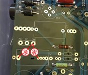
I remember using the center GND pad to connect the caps, as I had a signal pin already soldered where you drew that diagram. I can't otherwise remember exactly how I connected the extra caps...
What I can tell you is that I increased R4 and R7, so that the B+ and B- dropped to about 120V. Well within range for the 6SN7, but more effective as an RC filter.
What I can tell you is that I increased R4 and R7, so that the B+ and B- dropped to about 120V. Well within range for the 6SN7, but more effective as an RC filter.
")
I have tried to figure out a hum issue on a Broskie phono preamp. Tried all the things here also nothing worked. Read the blog from alexcp and that sounds promising. One thing the attachments from the blog say they are corrupted and will not open. Can anybody check that out or repost here?
Sorry about the blog post attachments. They used to be ok but seem to be corrupted now. I may be able to re-post them some time soon but I need to recreate them. One PDF was just the appropriate schematic from the board's manual, the other was the same schematic with extra caps as described in the text.
Having said that, what phono preamp you are fighting with? Broskie's "Aikido" in single supply schematics - which I believe include at least some of his phono preamps - is based on a different principle then the "Aikido" in dual supply schematics. My post about "Removing hum from Aikido Cathode Follower (ACF-2 9-Pin)" deals with the latter and would not be useful for the former.
Having said that, what phono preamp you are fighting with? Broskie's "Aikido" in single supply schematics - which I believe include at least some of his phono preamps - is based on a different principle then the "Aikido" in dual supply schematics. My post about "Removing hum from Aikido Cathode Follower (ACF-2 9-Pin)" deals with the latter and would not be useful for the former.
- Status
- This old topic is closed. If you want to reopen this topic, contact a moderator using the "Report Post" button.
- Home
- Amplifiers
- Tubes / Valves
- Glassware ACF-2 Aikido hum problem