Even me and my friend are having the same hum issue since more than 2 years that we built the ACF-2 with Tungsol 6SN7 tubes. We have even tried with different NOS set of tubes but no difference with the hum. Its actually annoying with high sensitive full rangers.
I have tried changing multiple transformers right from the toroidal to RCORE to EI cores and with different voltages and still could not get rid of the hum. I have tried with 120-0-120v 100mA + 12-0-12v 2A (3A, 4A, 5A). Also powering with individual transformers for heater and B+. Also tried using a ground loop breaker with couple of diodes+caps+resistors (which worked for my power amp hum) but did not had any effect on the hum issues.
We have reached out to John on the same but he could only respond back saying its the ground loop issue, but I believe its something else and not the ground loop issue. As per John's recommendation and various threads I have configured the PSU section for full-wave-center-tap. But couple of weeks ago read somewhere that changing it to full-wave bridge may improve the hum, so did the same by adding couple of caps and diodes. Forgot to use the AC secondary voltage of 0-12V for this configuration and instead used 12-12v and because of the double the voltage one of the 10000uf 16v cap blew up
Replaced this cap and now ran at the correct voltage of 0-12V without the CT pin. Not sure what else has blown previously that there is no voltage on the 7 & 8 pins of the tube sockets. It just shows 0.00v.
Got fed up with this board with too much tinkering and unable to resolve the hum issues. Now looking at this thread just realized that I am not the only one who is facing these issues with the ACF-2 Octal board there are many out there
What tubes did you use with it? Someone said they always had problems with 6SN7, but 6SL7 was dead quiet.
I was using 6SN7 but I can have a bunch of 6SL7 that I can try out. Just need to find some transformers to get it powered up.
I do not have any bridge rectifiers near the circuit, I used discrete diodes for my loop breaker.
KC
Mine came with an integrated rectifier that had a spot on the board. Its outputs are shorted and the inputs seem to be across C19.
I had my own filter made as well, but then I realized the extra parts on the board have the same role. By extra parts I mean the rectifier and a ceramic cap labeled C32.
I’m gonna remove this rectifier and see how that impacts the system. Up until now, having fixed some build issues I had, I can say that grounding the circuit to mains earth or not doesn’t actually affect the sound
I swapped the cathode resistors to the value recommended for 6SL7 in the manual, 680R, and installed a pair of 6SL7s to see what would happen. Not surprisingly I am having the same results.
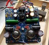
I've attached a picture of the board that I am using for reference.
Any recommendations on testing the PSU circuits for oscillation?
I've attached a picture of the board that I am using for reference.
Any recommendations on testing the PSU circuits for oscillation?
Attachments
That’s interesting. You have the v1 board, I have the v2 board. I have spotted some differences. Namely, I don’t have a C7 on the board... that’s where the pesky rectifier sits. At the same time, we both have a C17 that’s not present on the schematic. Either way, we have the same problem, which is extremely interesting.
I’ll have a better look tomorrow, when I’m fresh. I’m thinking about ordering a cheapo oscilloscope from ebay. Found some decent ones for 25 bucks... they may not be professional quality, but I think I can get some value out of it for home use.
@nautibuoy if you can snap some pics of the PCB with as little parts on it as possible, that would be helpful. I’d try to trace some tracks, as it seems there are slight deviations from the schematic. Thanks!
Last edited:
@nautibuoy if you can snap some pics of the PCB with as little parts on it as possible, that would be helpful.
Sorry, I've almost finished assembling my ACF-2 PCB. My board is Rev. B, which includes the "pesky rectifier" and associated cap C32. (I don't see the rectifier as pesky, it is just providing you with an on-PCB option for coupling ACF-2 ground to chassis ground.)
I am planning to use NOS 6SN7 tubes, configured as per the 'typical part values' on page 5 of the manual. Filament supply is configured as full-wave bridge and will be running at 12.6V.
Ah, damn. Oh well. My problem with the rectifier is that it seems to have a connection to C19+ instead of - (which would be CT/circuit ground). I can’t tell exactly though, as the tracks are covered by parts. If I’m mistaken, it’s all good.
I’m running the heater in voltage doubler mode, as I only have a 6.3Vac supply. I had it in full wave bridge with heaters in parallel and my voltage was slightly lower and, presumably, unregulated.
Anyway, let us know how this works out for you. I am really curious.
@dhtrob it is... but at one point I was running it with a cable that didn’t have a ground connection (not on purpose) and there wasn’t any change. Anyway, I tried it in every configuration possible... still no luck.
Last edited:
I suspect this is a grounding issue.
Just to clarify, you have J6 linked? If so (assuming you have metal PCB stand-offs connected to your chassis) you have directly connected the ACF-2 ground to your chassis ground.
Rather than making guesses about what might, or might not, be the issue go back to basics. I suggest to start with you;
1. Disconnect ACF-2 ground from chassis ground entirely (remove J6 and and other wires to chassis ground).
2. Reference page 12 of the manual (I think this is the hook-up approach you've followed) and double check all the connections and ensure all of your input/output sockets are isolated from the chassis, etc.. Personally I would also twist the signal wire pairs together more tightly - may make no difference but at least the job will have been done well. You could also consider screening these wires (connecting the screen at one end only).
3. Reference page 14 of the manual and execute the steps set out in the 'Testing' section. Post the results.
With my own project I was planning to get the DAC section working first, however given this discussion topic I will try to complete my ACF-2 board assembly and start walking through the page 14 tests as soon as I can find the time.
Ah, damn. Oh well. My problem with the rectifier is that it seems to have a connection to C19+ instead of -
Nope, the rectifier doesn't connect to C19+, just ACF-2 ground and the house ground pad.
We have reached out to John on the same but he could only respond back saying its the ground loop issue, but I believe its something else and not the ground loop issue. As per John's recommendation and various threads I have configured the PSU section for full-wave-center-tap. But couple of weeks ago read somewhere that changing it to full-wave bridge may improve the hum, so did the same by adding couple of caps and diodes. Forgot to use the AC secondary voltage of 0-12V for this configuration and instead used 12-12v and because of the double the voltage one of the 10000uf 16v cap blew up
Replaced this cap and now ran at the correct voltage of 0-12V without the CT pin. Not sure what else has blown previously that there is no voltage on the 7 & 8 pins of the tube sockets. It just shows 0.00v.
Any idea where do I start looking at with the issue at the B+ side as there is no voltage coming on the tube sockets?
Thanks
I suspect this is a grounding issue.
Just to clarify, you have J6 linked? If so (assuming you have metal PCB stand-offs connected to your chassis) you have directly connected the ACF-2 ground to your chassis ground.
Rather than making guesses about what might, or might not, be the issue go back to basics. I suggest to start with you;
1. Disconnect ACF-2 ground from chassis ground entirely (remove J6 and and other wires to chassis ground).
2. Reference page 12 of the manual (I think this is the hook-up approach you've followed) and double check all the connections and ensure all of your input/output sockets are isolated from the chassis, etc.. Personally I would also twist the signal wire pairs together more tightly - may make no difference but at least the job will have been done well. You could also consider screening these wires (connecting the screen at one end only).
3. Reference page 14 of the manual and execute the steps set out in the 'Testing' section. Post the results.
With my own project I was planning to get the DAC section working first, however given this discussion topic I will try to complete my ACF-2 board assembly and start walking through the page 14 tests as soon as I can find the time.
Yes, it does sound like a grounding issue. However, it seems like a very subtle problem, reproduced by 3 people with 2 different board revisions.
In my case, I tried it both with J6 linked and unlinked. I do have metal standoffs and I did check for continuity, just to be sure.
Yesterday, I noticed that the mains inlet was connected to the chassis via the 3rd fin (mains ground), but also it's own chassis, effectively making an earth ground loop, short as it were. I therefore removed the wire from the 3rd fin to the chassis and now it only has one connection. This did not make any change regarding hum.
I have checked all connections to be isolated from the chassis, so that's out of the question. I also checked the input selector and volume pot. Everything is isolated from the chassis (and yes, I have followed instructions on page 12). Wires have been twisted tightly (since the original picture), both signal and mains. I have also screened one of the output cables, with the screen only tied to ground at the source. I left the other one twisted only so I can A/B. I have also shorted the board inputs. Nothing gets rid of the hum though... I mean there's literally no change, ever so minor.
My only idea at this point, seeing as you have checked the rectifier is not connected to C19+, is that I should try it with the board completely out of the enclosure and not connected to mains earth. This is slightly difficult though, as I have a lot of things to take apart, and I'll probably have some time to do it next weekend.
In the meantime, I look forward to hearing your experience with the board. I'd be really happy to hear you don't have an issue with the hum.
Any idea where do I start looking at with the issue at the B+ side as there is no voltage coming on the tube sockets?
Thanks
What you've described isn't a B+ issue but a heater supply fault - are we talking about different things?
If you fed the filament supply 24V AC I suspect you will need to replace more parts than just the cap that blew. You'll have stressed the other cap and maybe blown the LT1085?
What you've described isn't a B+ issue but a heater supply fault - are we talking about different things?
If you fed the filament supply 24V AC I suspect you will need to replace more parts than just the cap that blew. You'll have stressed the other cap and maybe blown the LT1085?
The LD1085 should be able to handle much more. I would think C30 is a problem... it's rated for 16V tops.
Any idea where do I start looking at with the issue at the B+ side as there is no voltage coming on the tube sockets?
Thanks
I would start by testing the heaters only, without the B supply connected.
Power it up and measure AC at the input pads. If that's ok, measure voltage across C28 and C29. If that's ok, measure the output of the regulator. If that's also, ok... check C30. If it failed and it's shorted, than that's your issue.
If your heaters are ok, start going the same way about the B supply, but be careful as you have much higher voltages.
My only idea at this point, seeing as you have checked the rectifier is not connected to C19+, is that I should try it with the board completely out of the enclosure and not connected to mains earth. This is slightly difficult though, as I have a lot of things to take apart, and I'll probably have some time to do it next weekend.
You don't need to remove the board from the chassis, just do what I suggested in #1.
Have you done what I suggested in #3 - if so what results did you get?
Yeah, I did #1... no dice.
Kind of did #3. I can't measure across C5 with the board inside the enclosure, I've got the tubes on one side and the parts on the other... you get the gist.
Across C4 I have 268 and 267V respectively.
Edit: Well that was something stupid of me to say, considering they're paralleled... it's enough to measure across C4... or use the empty spot for C6. Anyway, thing is I have the correct voltage.
Last edited:
The LD1085 should be able to handle much more. I would think C30 is a problem... it's rated for 16V tops.
Rectifying 24VAC will result in around 34VDC (could be more than 24VAC depending on transformer regulation etc.) which I imagine is close to the max input voltage of an LT1085. Anyway, it's best not to guess or assume what might or might not have failed but to work through systematically to identify and fix any faults.
Rectifying 24VAC will result in around 34VDC (could be more than 24VAC depending on transformer regulation etc.) which I imagine is close to the max input voltage of an LT1085. Anyway, it's best not to guess or assume what might or might not have failed but to work through systematically to identify and fix any faults.
Yes, agreed.
Yeah, I did #1... no dice.
So to confirm, your ACF-2 ground is now totally isolated from the chassis ground?
Kind of did #3. I can't measure across C5 with the board inside the enclosure, I've got the tubes on one side and the parts on the other... you get the gist.
Across C4 I have 268 and 267V respectively.
C4 and C5 are in parallel so the B+/- voltages look OK.
So where are the rest of the results from the testing section, i.e. what voltage are the heaters seeing?
- Status
- This old topic is closed. If you want to reopen this topic, contact a moderator using the "Report Post" button.
- Home
- Amplifiers
- Tubes / Valves
- Glassware ACF-2 Aikido hum problem