"......since the two primary windings are unity coupled there is no longer any need for sectionalizing the primary as is common in high quality transformers today. This results in an economy in manufacture."
Extract from Audio Engineering magazine Dec.1949 , written by Frank McIntosh and his ingenious alien assistant Gordon Gow (Canada) .He is the inventor of the unity coupled circuit.
AUDIO - Consumer audio and music magazine from late 40's to 2000.
Did you hear what G.G. said ,no sectionizing ,hence no sandwiches, no pizza slices .Just wind a primary first as it's name indicates and cover it with a secondary, the other pair in a symmetric compartment, and you'll get 200khz frequency response ,30khz PBW.
Don't you believe it.
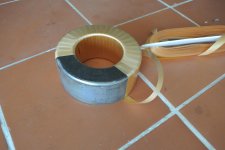
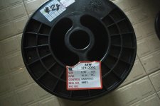
To try this unity coupled circuit out, I bought a 500VA toroide transformer for OPT, 600 Baht and a 300VA for IT ,400 Baht from AMORN group Thailand . (33baht =1$) .For the power supply I already have a300VA which had it's primary cut due to fall. In fact it is by dismantling it I found out that it's primary is wound in bifillar, for the simple reason that the interior circumference is half of the exterior.To fill external surface completely the two wires overlap internally and interleave externally .By this the two layers in series makes 110V ac in between. I seperated the two layers and applied 600V dc by a doubler from the mains 220V . For 48 hours ,absolutly nothing happened to the sacrificial series resistor .So, I decided that this is the wire necessary for biffilar winding. It is not AWG nor SWG but 200°C version AEW. I didn't have any difficulty to find it ,as a nearby spare parts vendor for professional handheld power tools , had such wires.It has 10% less copper but thicker insulator.It cost the same price as SWG ,400baht per kg. I bought 1½kg AEW No 28 and 1kg of SWG No 21 copper diameters of 0.38 and 0.8 mm.
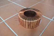
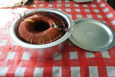
The transformers put to nude (wires can be sold as scrap metal ) The 500VA core measured 65 mm internal diameter and 117mm external ,50mm high. This gives a cross section of 13cm sq. or 2 in.sq. This is half of what is used by McIntosh shown on the cover of the magazine.
Original winding measured 560 turns for 220V/50Hz ,this gives 850turns for 130V/20Hz for each of four primaries ,induction intensity about 1.9T.Giving a ratio of 6:1 the 8 ohms secondary gets 141 turns ,decomposed 100 +41turns for 4 ohms tap .
The core once prepared (edges rounded ,varnished and isolated) the toroid get devided into two halves ,excluding a tiny sector of three turns wide for extra trim and feedback .
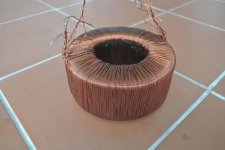
The architcture is 2 independent secondaries 0 4 8 ohms each wound on each half of the donut toppled each by a bifillar primary and decorated by another layer of secondary (S P S).
3 wires of 0.8mm wound 100 turns each join the opposite 4 ohms tap ,each side is in mirror symmetry ,forming 3 layers interior and 1½ layer external. The ½ external layers are nearly completed with 2 x 41 turns wound 2 wires in hand ,to join the 8 ohms back with 0, forming another internal layer.In total 4 layers internal ,2 external.
Varnished at each stage and a belt of araldite in the last interior layer ,the secondaries are isolated to wind the primaries ,2 x 850 turns biffiler, with single wire in hand in 5 layers loosing 10turns on each,varnished and isolated in between . The second primary is not mirror symmetry.
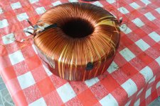
I added an extra 50 turns to each cathode windings on a 6th layer for class B2 .The reserved wedge got 10turns of 0.8mm and 2 x 4 turns 0.38mm for the feedback. The cylinder got wrapped only on its external side by two layers of 0.1mm 50mm wide isolator and the normal isolator covers all in double layer,totaling 0.5mm at external, to have low capacitance between the high impedance primaries and the last sandwiching secondaries to wind in single layer external, double internal.with single wire 100 +41turns. 0V ac terminals of the primaries are at the beginning.
The result:
impedance of primary PP :1kohms.(load for each tube)
ratio: 12:1 at 8 ohms nominal with Re 6ohms
f-3db due to mutual inductance 64Khz 20uH at 8 ohms
f-3db due to shunting capacitor 700khz 430pf at each primary or 215pf PP
primary inductance PP measured with 48V/50Hz on 8 ohms (50ma)=440H eq. to 116V/20Hz on each primary.
Rp for each primary 23.9 ohms
Rs at 8 ohms 0.1ohms
capacitance between two primary bifillar windings 24nF
possible output impedance 4 8 16 32
Total weight about 5Kg.
Total cost with aluminum kitchenware housing ,about 1200 Baht or 36$
time spent :18 days in reason of 3 hours a day (rainy season).
The interstage transformer is similar to the primary windings except it has 1800 turns for each side. I finished one side and 2 layers on the other as the rainy season is over.It measures 2ma with220V/50hz ,that is 44kohms/20Hz per plate ,170kohms PP.The required impedance is 100kohms PP 20Hz -30Khz for 6j5 (Rp 12kohms).I will be using 12bh7 (Rp 5800) and 5687 (Rp 3000) .Yes ,I know it is too much,but the advantage of toroide ,the more you wind ,the lower is the capacitance and higher the inductances. As the mutual inductance has less importance here ,if I get 16Khz mutual responce with 5687, that is less than 3mH, I will be satisfied.
Thank you G.G.
PS : This is just the beginning for the opt,as the capacitance is very low on primaries, there are more possibilities to reduce the mutual inductance.However ,it needs a colar to squeeze the donut tighter.
100Khz PowerBW is at reach.
KOKORIANTZ
Extract from Audio Engineering magazine Dec.1949 , written by Frank McIntosh and his ingenious alien assistant Gordon Gow (Canada) .He is the inventor of the unity coupled circuit.
AUDIO - Consumer audio and music magazine from late 40's to 2000.
Did you hear what G.G. said ,no sectionizing ,hence no sandwiches, no pizza slices .Just wind a primary first as it's name indicates and cover it with a secondary, the other pair in a symmetric compartment, and you'll get 200khz frequency response ,30khz PBW.
Don't you believe it.
To try this unity coupled circuit out, I bought a 500VA toroide transformer for OPT, 600 Baht and a 300VA for IT ,400 Baht from AMORN group Thailand . (33baht =1$) .For the power supply I already have a300VA which had it's primary cut due to fall. In fact it is by dismantling it I found out that it's primary is wound in bifillar, for the simple reason that the interior circumference is half of the exterior.To fill external surface completely the two wires overlap internally and interleave externally .By this the two layers in series makes 110V ac in between. I seperated the two layers and applied 600V dc by a doubler from the mains 220V . For 48 hours ,absolutly nothing happened to the sacrificial series resistor .So, I decided that this is the wire necessary for biffilar winding. It is not AWG nor SWG but 200°C version AEW. I didn't have any difficulty to find it ,as a nearby spare parts vendor for professional handheld power tools , had such wires.It has 10% less copper but thicker insulator.It cost the same price as SWG ,400baht per kg. I bought 1½kg AEW No 28 and 1kg of SWG No 21 copper diameters of 0.38 and 0.8 mm.
The transformers put to nude (wires can be sold as scrap metal ) The 500VA core measured 65 mm internal diameter and 117mm external ,50mm high. This gives a cross section of 13cm sq. or 2 in.sq. This is half of what is used by McIntosh shown on the cover of the magazine.
Original winding measured 560 turns for 220V/50Hz ,this gives 850turns for 130V/20Hz for each of four primaries ,induction intensity about 1.9T.Giving a ratio of 6:1 the 8 ohms secondary gets 141 turns ,decomposed 100 +41turns for 4 ohms tap .
The core once prepared (edges rounded ,varnished and isolated) the toroid get devided into two halves ,excluding a tiny sector of three turns wide for extra trim and feedback .
The architcture is 2 independent secondaries 0 4 8 ohms each wound on each half of the donut toppled each by a bifillar primary and decorated by another layer of secondary (S P S).
3 wires of 0.8mm wound 100 turns each join the opposite 4 ohms tap ,each side is in mirror symmetry ,forming 3 layers interior and 1½ layer external. The ½ external layers are nearly completed with 2 x 41 turns wound 2 wires in hand ,to join the 8 ohms back with 0, forming another internal layer.In total 4 layers internal ,2 external.
Varnished at each stage and a belt of araldite in the last interior layer ,the secondaries are isolated to wind the primaries ,2 x 850 turns biffiler, with single wire in hand in 5 layers loosing 10turns on each,varnished and isolated in between . The second primary is not mirror symmetry.
I added an extra 50 turns to each cathode windings on a 6th layer for class B2 .The reserved wedge got 10turns of 0.8mm and 2 x 4 turns 0.38mm for the feedback. The cylinder got wrapped only on its external side by two layers of 0.1mm 50mm wide isolator and the normal isolator covers all in double layer,totaling 0.5mm at external, to have low capacitance between the high impedance primaries and the last sandwiching secondaries to wind in single layer external, double internal.with single wire 100 +41turns. 0V ac terminals of the primaries are at the beginning.
The result:
impedance of primary PP :1kohms.(load for each tube)
ratio: 12:1 at 8 ohms nominal with Re 6ohms
f-3db due to mutual inductance 64Khz 20uH at 8 ohms
f-3db due to shunting capacitor 700khz 430pf at each primary or 215pf PP
primary inductance PP measured with 48V/50Hz on 8 ohms (50ma)=440H eq. to 116V/20Hz on each primary.
Rp for each primary 23.9 ohms
Rs at 8 ohms 0.1ohms
capacitance between two primary bifillar windings 24nF
possible output impedance 4 8 16 32
Total weight about 5Kg.
Total cost with aluminum kitchenware housing ,about 1200 Baht or 36$
time spent :18 days in reason of 3 hours a day (rainy season).
The interstage transformer is similar to the primary windings except it has 1800 turns for each side. I finished one side and 2 layers on the other as the rainy season is over.It measures 2ma with220V/50hz ,that is 44kohms/20Hz per plate ,170kohms PP.The required impedance is 100kohms PP 20Hz -30Khz for 6j5 (Rp 12kohms).I will be using 12bh7 (Rp 5800) and 5687 (Rp 3000) .Yes ,I know it is too much,but the advantage of toroide ,the more you wind ,the lower is the capacitance and higher the inductances. As the mutual inductance has less importance here ,if I get 16Khz mutual responce with 5687, that is less than 3mH, I will be satisfied.
Thank you G.G.
PS : This is just the beginning for the opt,as the capacitance is very low on primaries, there are more possibilities to reduce the mutual inductance.However ,it needs a colar to squeeze the donut tighter.
100Khz PowerBW is at reach.
KOKORIANTZ
Attachments
The patent and the article were about the sectioning of the primaries related to the two halves of the push-pull. This was solved with bifilar windings.
The sectioning between primaries and secondaries is still required otherwise suboptimal coupling will occur despite the fact a toroid has potentially the minimum leakage of all cores.
The sectioning between primaries and secondaries is still required otherwise suboptimal coupling will occur despite the fact a toroid has potentially the minimum leakage of all cores.
f-3db due to mutual inductance 64Khz 20uH at 8 ohms
f-3db due to shunting capacitor 700khz 430pf at each primary or 215pf PP
Hard to understand what you are talking about....
I don't believe you get TOTAL 20 microH leakage inductance. Maybe you are referring to leakage between primaries? That's fine and better than what is required for optimal perfmance of class B Unity Coupling. But then you have much more leakage between primaries and secondaries especially with that simple arrangment.
If you really had total 20uH leakage inductance in total and 430pF shunt capacitance resonance would be better than 1.7 MHz and f(-3dB) not too far...!!!
If shunt capacitance is really 430 pF and f-3dB is 64KHz, leakage inductance due to primaries and secondary arrangment is no less than 14 mH.
diy unity coupled OPT
In 1954, at univesity of Cincinnati ,the same city hosted McIntosh in 1946 , a student produced a thesis for BE degree . He redesigned the 50W-2 using a third wire in the primaries for the screen grid, powering it by 300V instead of 440V ( max is 270V for 6L6). He did wind by hand himself this trifilar transformer adopting ppp-S-ppp pattern .The P-S-P pattern commonly used by PA amplifiers as Jefferson's, can deliver at best 12khz. Despite 1/3 of the primary volume occupied by enactive SG windings ,despite he stuffed 13 isolators for the secondary, where none is needed ,but thanks to unity coupled technique ,he gets 40Khz frequency response and 20Khz PBW .This showes how ,without sectionalizing ,anyone can wind easily high performance unity coupled OPT with C core.
https://archive.org/details/A_McIntosh_Audio_Amplifier_Incorporating_a_Trifilar_Output_Transformer_Thesis_Hu
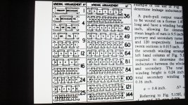
Winding on toroid is cheaper ,but much more difficult. The surface core-windings is three times more than double C core . If I wind the same as McIntosh 2x (pp-S), my shunting capacitance would be three times higher ,limiting the PBW at 10Khz. This why I went against the trend and wound it 2x (S-pp -S ),unknown to winder's chart, it gives 16 mutual inductances paralleled ,linking 4 primaries to each 4 secondaries instead of 8 mutuals for 2x(pp-S).
Result ,constant 64Khz frequency respose at any power .
KOKORIANTZ
In 1954, at univesity of Cincinnati ,the same city hosted McIntosh in 1946 , a student produced a thesis for BE degree . He redesigned the 50W-2 using a third wire in the primaries for the screen grid, powering it by 300V instead of 440V ( max is 270V for 6L6). He did wind by hand himself this trifilar transformer adopting ppp-S-ppp pattern .The P-S-P pattern commonly used by PA amplifiers as Jefferson's, can deliver at best 12khz. Despite 1/3 of the primary volume occupied by enactive SG windings ,despite he stuffed 13 isolators for the secondary, where none is needed ,but thanks to unity coupled technique ,he gets 40Khz frequency response and 20Khz PBW .This showes how ,without sectionalizing ,anyone can wind easily high performance unity coupled OPT with C core.
https://archive.org/details/A_McIntosh_Audio_Amplifier_Incorporating_a_Trifilar_Output_Transformer_Thesis_Hu
Winding on toroid is cheaper ,but much more difficult. The surface core-windings is three times more than double C core . If I wind the same as McIntosh 2x (pp-S), my shunting capacitance would be three times higher ,limiting the PBW at 10Khz. This why I went against the trend and wound it 2x (S-pp -S ),unknown to winder's chart, it gives 16 mutual inductances paralleled ,linking 4 primaries to each 4 secondaries instead of 8 mutuals for 2x(pp-S).
Result ,constant 64Khz frequency respose at any power .
KOKORIANTZ
Attachments
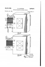

Reference the patent
Patent US2477074 - Wide band amplifier coupling circuits - Google Patents
Patent US2477074 - Wide band amplifier coupling circuits - Google Patents
I'd like more information about this transformer that you made. Did you put it into a working amplifier?
Can this be wired directly to a MC240 or MC275 as a replacement for their stock transformers?
Can this be wired directly to a MC240 or MC275 as a replacement for their stock transformers?
"......since the two primary windings are unity coupled there is no longer any need for sectionalizing the primary as is common in high quality transformers today. This results in an economy in manufacture."
Extract from Audio Engineering magazine Dec.1949 , written by Frank McIntosh and his ingenious alien assistant Gordon Gow (Canada) .He is the inventor of the unity coupled circuit.
AUDIO - Consumer audio and music magazine from late 40's to 2000.
Did you hear what G.G. said ,no sectionizing ,hence no sandwiches, no pizza slices .Just wind a primary first as it's name indicates and cover it with a secondary, the other pair in a symmetric compartment, and you'll get 200khz frequency response ,30khz PBW.
Don't you believe it.
To try this unity coupled circuit out, I bought a 500VA toroide transformer for OPT, 600 Baht and a 300VA for IT ,400 Baht from AMORN group Thailand . (33baht =1$) .For the power supply I already have a300VA which had it's primary cut due to fall. In fact it is by dismantling it I found out that it's primary is wound in bifillar, for the simple reason that the interior circumference is half of the exterior.To fill external surface completely the two wires overlap internally and interleave externally .By this the two layers in series makes 110V ac in between. I seperated the two layers and applied 600V dc by a doubler from the mains 220V . For 48 hours ,absolutly nothing happened to the sacrificial series resistor .So, I decided that this is the wire necessary for biffilar winding. It is not AWG nor SWG but 200°C version AEW. I didn't have any difficulty to find it ,as a nearby spare parts vendor for professional handheld power tools , had such wires.It has 10% less copper but thicker insulator.It cost the same price as SWG ,400baht per kg. I bought 1½kg AEW No 28 and 1kg of SWG No 21 copper diameters of 0.38 and 0.8 mm.
The transformers put to nude (wires can be sold as scrap metal ) The 500VA core measured 65 mm internal diameter and 117mm external ,50mm high. This gives a cross section of 13cm sq. or 2 in.sq. This is half of what is used by McIntosh shown on the cover of the magazine.
Original winding measured 560 turns for 220V/50Hz ,this gives 850turns for 130V/20Hz for each of four primaries ,induction intensity about 1.9T.Giving a ratio of 6:1 the 8 ohms secondary gets 141 turns ,decomposed 100 +41turns for 4 ohms tap .
The core once prepared (edges rounded ,varnished and isolated) the toroid get devided into two halves ,excluding a tiny sector of three turns wide for extra trim and feedback .
The architcture is 2 independent secondaries 0 4 8 ohms each wound on each half of the donut toppled each by a bifillar primary and decorated by another layer of secondary (S P S).
3 wires of 0.8mm wound 100 turns each join the opposite 4 ohms tap ,each side is in mirror symmetry ,forming 3 layers interior and 1½ layer external. The ½ external layers are nearly completed with 2 x 41 turns wound 2 wires in hand ,to join the 8 ohms back with 0, forming another internal layer.In total 4 layers internal ,2 external.
Varnished at each stage and a belt of araldite in the last interior layer ,the secondaries are isolated to wind the primaries ,2 x 850 turns biffiler, with single wire in hand in 5 layers loosing 10turns on each,varnished and isolated in between . The second primary is not mirror symmetry.
I added an extra 50 turns to each cathode windings on a 6th layer for class B2 .The reserved wedge got 10turns of 0.8mm and 2 x 4 turns 0.38mm for the feedback. The cylinder got wrapped only on its external side by two layers of 0.1mm 50mm wide isolator and the normal isolator covers all in double layer,totaling 0.5mm at external, to have low capacitance between the high impedance primaries and the last sandwiching secondaries to wind in single layer external, double internal.with single wire 100 +41turns. 0V ac terminals of the primaries are at the beginning.
The result:
impedance of primary PP :1kohms.(load for each tube)
ratio: 12:1 at 8 ohms nominal with Re 6ohms
f-3db due to mutual inductance 64Khz 20uH at 8 ohms
f-3db due to shunting capacitor 700khz 430pf at each primary or 215pf PP
primary inductance PP measured with 48V/50Hz on 8 ohms (50ma)=440H eq. to 116V/20Hz on each primary.
Rp for each primary 23.9 ohms
Rs at 8 ohms 0.1ohms
capacitance between two primary bifillar windings 24nF
possible output impedance 4 8 16 32
Total weight about 5Kg.
Total cost with aluminum kitchenware housing ,about 1200 Baht or 36$
time spent :18 days in reason of 3 hours a day (rainy season).
The interstage transformer is similar to the primary windings except it has 1800 turns for each side. I finished one side and 2 layers on the other as the rainy season is over.It measures 2ma with220V/50hz ,that is 44kohms/20Hz per plate ,170kohms PP.The required impedance is 100kohms PP 20Hz -30Khz for 6j5 (Rp 12kohms).I will be using 12bh7 (Rp 5800) and 5687 (Rp 3000) .Yes ,I know it is too much,but the advantage of toroide ,the more you wind ,the lower is the capacitance and higher the inductances. As the mutual inductance has less importance here ,if I get 16Khz mutual responce with 5687, that is less than 3mH, I will be satisfied.
Thank you G.G.
PS : This is just the beginning for the opt,as the capacitance is very low on primaries, there are more possibilities to reduce the mutual inductance.However ,it needs a colar to squeeze the donut tighter.
100Khz PowerBW is at reach.
KOKORIANTZ
I discourage you to wind by yourself this transformer, if, as me, you have delicate fingers, it took two months to have the articulations of my thumbs to heel. As financialy you have more means , I firmly advise you to use double C cores , as in Europe you don't have high shipment cost . The patent that I show above post gives all the details of winding and it is very easy . It is simple two wires in hand winding linear (no secterizing) covered by the secondary . Yes , the wires are not ordinary (200°C) used commonly in high quality hand held tools, you must search for . If you find motor,transformer rewinders in your country, they can wind it for you . In Bangkok ,a street rewinder asked only 5$ , carcasse and wires mica isolator provided by me .
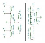
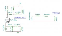
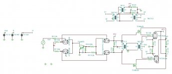
The amplifier is still under design . The circuit shown bellow is the actual stage . By adding mosfets on the screengrids pulled the power to 80 watts (wthout SG 100 ohm resistors) , driving the 6L6GCs (RCA type) both grid and screengrid. The sound of this type of amp depends highly on the driver's , as the output is neary voltage follower. The 12BH7 is RCA with expending character , in order to keep it's nature , the amp does't have voltage feedback but positive current one to give a damping factor of 10. With 6BX7 I get also very interesting sound .
Tina simulator doesn't have both primary and secondary center point transformer model . For that I had to use two transformers and individual inductor for each winding which makes it look complicated , but the output stage is identical to MC50w2.
Attachments
- Status
- This old topic is closed. If you want to reopen this topic, contact a moderator using the "Report Post" button.
- Home
- Amplifiers
- Tubes / Valves
- Winding Unity Coupled Toroid OPT+IT