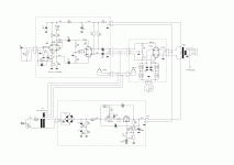
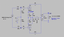
From what I can find 6SA7 and 6N13S are different tubes in some respects. I have yet to find specs for 6N13S in push pull. 2A3 and 300b distortion specs are similar to 6N13S especially in cathode bias. Atmas-Sphere claims less than 1% THD although that's an OTL amp and mine is not. I am curious to know what the distortion specs for Winged 'C' 6N13S are?
Also, if I'm correct in reading the load line, at 60ma and 250 volts B+ I'm just under the dissipation curve and just above the distorted curved section of the load lines. It's a compromise.
Also, if I'm correct in reading the load line, at 60ma and 250 volts B+ I'm just under the dissipation curve and just above the distorted curved section of the load lines. It's a compromise.
Last edited:
taken from the plate charts with consideration of 250V is a max B+ for 6080...
To avoid confusion, B+ (supply voltage) is not the same as plate (to cathode) voltage. The maximum plate voltage for 6080 is specified as 250 V.
In case of cathode bias, the supply voltage is the sum of plate and cathode voltage.
Operating 6080 with cathode bias from 250 V supply voltage is far from optimum.
As mentioned in some references of the original tube manufacturers, the optimum condition for 6080 as PP-amplifier is Ua = 250 V, Ia = 50 mA, Ra-a = 5k.
This require some 370...380 V as B+ when recommended autobias is used.
With lower supply voltage or lower Ra-a, either output power will be smaller or THD will be higher.
From what I can find 6SA7 and 6N13S are different tubes in some respects.
What difference have you noticed ?
I can not find any essential difference between the data of these types.
If I swap between 6N13S and 6080 in my amplifier I get similar result in terms of output power and THD.
I am curious to know what the distortion specs for Winged 'C' 6N13S are?
It is similar to 6080/6AS7G, i.e. the optimum THD you can expect is some 4% of THD, mainly 3rd harmonic. This is the THD generated by the PP-output stage alone.
As I have earlier mentioned, the total THD can be essentially lowered by the proper desing of the driver stage, without GNFB.
I got the reduction from 4% to some 1% with the distortion cancelling by the driver stage.
Here you can find many useful documents, two attachments at the second post, one at 10th and 3 at post 13.:
Article Wanted - "High Quality Amplifier with the 6AS7G" by McProud
Last edited:
Thanks Artsalo, I read the articles you suggested. Am I right in assuming that the "Dynamic noise suppression" section of the amplifier is what you were referring to in the earlier post? That seems more complicated than the amplifier itself. At 250 volts plate to cathode and 50ma I'm looking at a cathode resistor of 1k. I have available with the current power supply 322 volts. In PPP then plate to plate will be 2500 ohms? That's good to know for when I order transformers.
As for the difference in the variants you are correct. The load line graphs for 6N13S do not extend out as far as 6AS7 and 6080. So I thought they were different they aren't.
I am surprised to hear about the third order distortion. I thought triodes were predominately 2nd order. Or is that taking into account PP canceling second order?
I was assuming much of the distortion would be cancelled by using the CCS is that not the case?
Ok, using the load lines of 6080 at 50ma I'll need an approximately 130 volt swing to drive 6N13S. At 15ma and 300volts B+ for 6n6p I can get more than that out of a single tube. The only drawback is I would need a 16 volt PP swing to drive the amplifier. I have an AR SP3a and an Arthur Loesch 6DJ8. Both of these preamps are capable of that kind of output.
Is there some reason power amps have to be drivable to maximum output with only one volt of input? Why not depend on the preamp to do the early voltage amplification instead of adding a step up or a third stage at the input?
Is there some reason power amps have to be drivable to maximum output with only one volt of input? Why not depend on the preamp to do the early voltage amplification instead of adding a step up or a third stage at the input?
Am I right in assuming that the "Dynamic noise suppression" section of the amplifier is what you were referring to in the earlier post?
No. I have told that the biasing of the driver stage has very big effect to the overall THD of the amplifier. The THD generated by the output stage can be canceled by the (reverse phase) THD of the driver stage.
At 250 volts plate to cathode and 50ma I'm looking at a cathode resistor of 1k.
At 250V/50mA the cathode voltage will be about 125 V and cathode resistor should be 2k5. This means that the supply voltage should be 250V + 125V = 375V.
Look at my schematic at the post #7.
With 322 V supply voltage you should use smaller cathode resistor. Then 250V/50mA can not be reached, but quite close.
In PPP then plate to plate will be 2500 ohms?
Yes.
I thought triodes were predominately 2nd order. Or is that taking into account PP canceling second order?
In general, triodes produce mainly 2nd order harmonics, but in case of push-pull, even harmonics are canceled at the output transformer. 6AS7 is a bit abnormal triode because it produces significant amount of 3rd harmonics too.
I was assuming much of the distortion would be cancelled by using the CCS is that not the case?
That happens with resistance couple and small signal stages, like preamps.
Ok, using the load lines of 6080 at 50ma I'll need an approximately 130 volt swing to drive 6N13S.
The maximum peak drive voltage (at A1 class) can be the same as grid voltage. In this case the grid is at -125 V, so the max. possible drive voltage is 125 Vp or 250 Vp-p or 88 Vrms.
I got 10 W with 68 Vrms drive.
Is there some reason power amps have to be drivable to maximum output with only one volt of input?
This is quite standard line level.
"No. I have told that the biasing of the driver stage has very big effect to the overall THD of the amplifier. The THD generated by the output stage can be canceled by the (reverse phase) THD of the driver stage."
Is that done by using an odd number of stages?
Is that done by using an odd number of stages?
Last edited:
Is that done by using an odd number of stages?
The number of stages is not essential. Only the driver stage and it's characteristics matter.
In this case, the PP output stage generate only odd harmonics and 3rd is the greatest.
This can be mostly canceled if such a signal is fed to the grids of the output tubes that generates (in the output stage) equal amplitude but reverse phase (180 deg.)
This simply happens when the 3rd harmonic distortion of the driver stage is at the same level as the 3rd harmonic distortion of the output stage. The 180 deg. phase shift takes place at the output stage since the signal is inverted there.
In single end amplifiers this phenomenon is much more visible. There 2nd harmonic levels are higher and canceling very effective.
Artsalo, the aforementioned biasing of the driver stage is that present in the schematic of post#7?
Yes it is. You can see that the plate voltage of the driver stage is relatively high (225V) compared to supply voltage (370V). Also cathode voltage of the driver stage is high.
So the driver tube is biased to non-linear operating point where it generates "suitable" harmonic content that together with the harmonic content of the output stage finally produce low overall THD.
Below is the link to the latest version of the schematic. The only difference is that now the driver stage has common cathode resistor. In the earlier version both tubes had separate resistors.
http://kuva.termiitti.com/image/43742.GIF
Attachments
Thanks, its a little clearer now. You are using the first half of 6SL7 as a voltage amplifier and the second half as a phase splitter. P2 is to even the output of the phase splitter? You seem to be underdriving the first tube and overdriving 6SN7 is that right? And if that is the case you must have reached this configuration by experimentation?
Can I assume that you are increasing all the harmonic distortion in the first stages. Allowing the push pull to cancel the even harmonics. And out of phase odd harmonics, in this case third, to cancel when they meet the inverted third order at the outputs?
Is the distortion created in the second 6SN7 stage?
Last edited:
P2 is to even the output of the phase splitter?
Yes, with P2 any imbalance in driver stage, output stage or OPT can be zeroed.
You seem to be underdriving the first tube and overdriving 6SN7 is that right?
The signal level is obviously lower at the 6SL7, because at 6SN7 the signal is amplified by previous stage.
I would not say that 6SN7 is overdriven, but it is biased to non-linear operating point.
And if that is the case you must have reached this configuration by experimentation?
My design procedure begin with several simulations with different topologies and after I have reached the target results, I continue by making a prototype. With the prototype I fine tune the circuit and make the required component modifications.
Can I assume that you are increasing all the harmonic distortion in the first stages.
The first stages, voltage amplifier and phase splitter, I design to most linear condition.
But as I have told, the driver stage (6SN7) is the key element to make the overall THD as low as possible. There some correct amount of harmonics are generated on purpose.
Allowing the push pull to cancel the even harmonics. And out of phase odd harmonics, in this case third, to cancel when they meet the inverted third order at the outputs?
Yes, exactly.
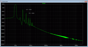
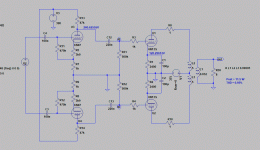
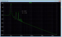
Below are some pictures to illustrate what happens when only the output stage is used and what happens when the driver stage is added too.
With output stage alone the THD = 4%, 3rd harmonic at level -29dB and 5th at -45db.
With output stage + driver the THD = 0.95%,, 3rd harmonic at level -45dB and 5th at -42 dB.
Attachments
Last edited:
In reading the Audio Express article I'm intrigued at the idea of using a toroidal power transformer as an output transformer. Since I won't be putting DC through the output transformer I'm planning to order only a 25VA transformer. And the 230 volt/primary 12 volt secondary Talema 62062 version. Using this transformer I'll have a 2.9 k primary into an 8 ohm load. And the fact that it is only $24 dollars is nice too! And in case it's a problem I'll leave space for a conventional transformer.
It's kinda amusing you are getting all same bumps along the way ))
In my SHAX project I mentioned that I auditioned several types/makes of small trafos. Talema did not sound best. I did not open it up, but assumably because of they are toroids the primaries have been wound one on top of another, which means noticeable imbalance of the output stage, even though you use CCSs. Unless you deliberately match the unmatched halves in one tube against the uneven resistance of primaries (ditch CCS) - that might work quite well.
AFAIR the resistance was 4-5% uneven. The secondaries most likely been wound bifilar as they are close on R. Maybe you should buy a cheapest one and open it up first, or someone who did is welcome to chime in on this question.
Besides, they saturate easier, and as I understand the totoidal OPTs are designed to defeat this, though, someone might find it acceptable to use the stock mains as OPTs.
On my subjective perception, you can get max 1/4 of nominal power spec of those, or for 25VA you do not expect it sound any good above 6 Wa.
That's why I opted for the trafos like this:
An externally hosted image should be here but it was not working when we last tested it.
I would use real pp-output transformers. Hammond or Edcor would be safe alternatives.
Here in Europe we have some local inexpensive alternatives but when shipped to USA they maybe are not anymore.
I have tested some power transformers, toroids and normal with EI-cores, but found no even reasonably performing one.
Usually the primary inductance is far too low (< 2H) for low distorted bass.
Sometimes the leakage inductance is too high and frequency response does not reach even 10 kHz.
What kind of test results did you get ?
Here in Europe we have some local inexpensive alternatives but when shipped to USA they maybe are not anymore.
I have tested some power transformers, toroids and normal with EI-cores, but found no even reasonably performing one.
Usually the primary inductance is far too low (< 2H) for low distorted bass.
Sometimes the leakage inductance is too high and frequency response does not reach even 10 kHz.
In my SHAX project I mentioned that I auditioned several types/makes of small trafos.
What kind of test results did you get ?
atrosalo, the TS is trying to keep the project at lowest budget so I'm just sharing out my observations and further contemplation on why this is that.
Of course the true OPT would give the best, but you are talking way too much of henries, khz, etc etc here. (Though, these make full sense for the general approach I listened a lot of praised amps that I'd like to never hear again)
So. .. results are mostly by my ear ))
Another forum member had a chance to hear that my amp and shared his impression of its pleasing sound. Yes, it does have HF and LF roll-offs, and the THD is few % before clipping, but it sounds as good as whatever you can get from 2 x 12AU7 driving a PP trafo.
In those measurement that I made, the best THD was 1-1.5% on 1KHz to a dummy resistive load at half way to clipping level. Other OPTs that I did not sonically like I did not bother to measure, why waste time.
I find this very surprising. I have never had a toroidal power transformer with less bandwidth than 10-20khz. What usually happens is the parasitics are much worse if the primaries are used in one direction rather than the other. If you wire them up the wrong way round you get a peak at between 30khz and 60khz. This saturates the core and severely compromises the low end response. Wire them up the other way and response is good out to 20khz and then falls off to a gentle peak at about 60khz, bass is Ok down to 10hz (not necessarily at full power though).I have tested some power transformers, toroids and normal with EI-cores, but found no even reasonably performing one.
Usually the primary inductance is far too low (< 2H) for low distorted bass.
Sometimes the leakage inductance is too high and frequency response does not reach even 10 kHz.
I have notices that different brands do indeed sound different and its usually attributable to this high frequency peaking. A 3db peak out at 50khz will sound very harsh and fatiguing even if you cannot directly hear it.
I can only think that your poor results are because you are trying to use them with a high rp valve. The 6080 is the ideal candidate for using toroidals since it has a the low output impedance necessary to bite into the relatively small henries.
Going with the smallest transfomer adequate for the job is a good idea since primary inductance will increase as core size decreases. 4x the expected power output seems a good rule of thumb.
Shoog
Last edited:
but you are talking way too much of henries, khz, etc etc here.
My approach to hifi amplifier design is based on real, measured performance, not on any image or opinion.
In case of hifi-amplifier all key features must be OK, such as distortion, frequency response, transient response, damping factor, S/N etc. etc.
When these are OK, the amplifier can not sound bad. Have you ever heard a bad sounding tube amplifier with faultless (measured) performance ?
I have not, but I have heard bad sounding amplifiers with poor measured performance.
The "design" method that contain no tests or analysis is - in my opinion - like guys at Boeing would design aircrafts with the target " it should be nice to fly".
Last edited:
I have never had a toroidal power transformer with less bandwidth than 10-20khz.
What has been the source impedance in these measurements ?
What usually happens is the parasitics are much worse if the primaries are used in one direction rather than the other.
How can you connect the primaries (of pp amp) the "other" way ?
bass is Ok down to 10hz (not necessarily at full power though).
To get good linearity below 100 Hz require much higher primary inductance than, say 2H. Even with some lower priced real output transformers the THD will increase rapidly below 100 Hz. The increase of THD does not happen due to saturation of the core (as usually is assumed), but because of too low primary inductance and therefore too low impedance for output tubes.
Last edited:
I have got these results with a 6080, PL86 and even a E55L.What has been the source impedance in these measurements ?
Buy a dual primary 0-115v,0-115v transformer and you have access to both ends of each winding. That makes it easy to switch winding direction. As such 115-0-115V transformers make poor candidates.How can you connect the primaries (of pp amp) the "other" way ?
The article which got me experimenting with power transformers was one of the early experimenters with all things DIY audio (the rediscoverer of the MATRIX topology) and he measured one brand of power toroidal as having over a 100henries of inductance. Also anything more than a few milliamps of current imbalance will cause significant saturation and kill response below 100hz stone dead. If you aren't prepared to run CCS to address it then forgety using toroidals.To get good linearity below 100 Hz require much higher primary inductance than, say 2H. Even with some lower priced real output transformers the THD will increase rapidly below 100 Hz.
It is my personal opinion that a power toroidal appropriately utilized will out perform most cheap OT's. What will kill its potential is not paying attention to the undoubtedly high parasitics that are present. They have their constraints but nothing that isn't easily addressed.
Shoog
Last edited:
Morgan Jones measured a standard Farnell part as having an inductance of 152 H. If you don't null the DC, as Shoog says, then this inductance will collapse.
It is hard to see how a mains x-former would work well with only a few Henries since it would be like putting a short circuit across the mains.
It is hard to see how a mains x-former would work well with only a few Henries since it would be like putting a short circuit across the mains.
Morgan Jones measured a standard Farnell part as having an inductance of 152 H
Do you have link to this ?
These big differences must be caused by the test method. The old one uses 5 Vrms at 50 or 60 Hz, but when the voltage is increased to some hundreds of volts the results will change a lot too.
I tested some PP-toroidal transformers of Polish manufacturer Toroidy a few years ago when they begun the manufacturing of audio transformers and I can say that the start was not easy. It took some test/modification turns before the performance was good.
Therefore to me it is difficult to believe that a random power transformer would simply be a good output transformer. As I said before, I have not been lucky to find one yet.
The inductances I mean are achieved with inductance meter with low voltages.
- Status
- This old topic is closed. If you want to reopen this topic, contact a moderator using the "Report Post" button.
- Home
- Amplifiers
- Tubes / Valves
- 6AS7GA as push pull output?
