Attachments
Has anyone built one of these amps?
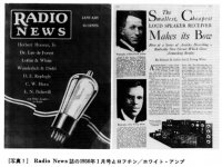
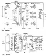
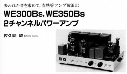
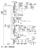
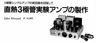
I used to think that the Japanese fetish was for 300B tubes. Looking back through more than 10 years worth of tube amp articles, see link, the fetish appears to be inductors. Transformers for input, interstage and output. Multiple power supply chokes of all sorts too. Wound components must be inexpensive in Japan or the guys that build the amps featured in the magazines might receive samples from the coil winders.
Regardless, it's all very impressive. Though I question the efficacy of several hundred dollars worth of "iron" in a 2 WPC power amp.
I don't imply that this coil fetish is a negative thing. Who in this forum doesn't like a good trannie, or even lots of them? Perhaps I'm just a little jealous.
Anyway, I've some spare "iron" looking for projects this winter so I think I'll have a kick at a Quad II-like EL84 amp and a transformer output line stage (heavily modified), see attachments.
If you can't look at all of these Japanese amps and be a little awe struck you might be in the wrong forum.
Thanks again Soundhappy.
Cheers, Steve
????????? HOME
Attachments
Attachments
-
 1890F0B2-9B1E-416C-9E7C-4F954946E42F.JPG401.7 KB · Views: 203
 -
 CA13EB4D-4B39-4E4E-8899-62E4AF2BBFF8.JPG420 KB · Views: 231
 -
 AEA0CF5B-ADE6-441B-8A1C-F4BC544B955E.JPG587.3 KB · Views: 167
 -
 2376973F-A6D4-4276-A36C-13A5FCBC4A11.JPG402.5 KB · Views: 66
 -
 65DE372B-9DC7-4CB9-8C7E-C2A2C23CD880.JPG402.1 KB · Views: 562
 -
 BCC805A6-6E98-428C-817F-A15E6F40F9C5.JPG290 KB · Views: 239
 -
 DE45D096-BE39-4DCC-B810-5295B11C965C.JPG194 KB · Views: 256
 -
 AA4520F8-AE4D-4A63-8AF2-BACDA1AC30B7.JPG514.1 KB · Views: 263
 -
 277B1043-1D2F-4B56-A03F-D91ADD4A44E3.JPG434.9 KB · Views: 255
For Your audio hobby inspiration 
Attachments
-
 1DBC0406-F1E8-4FF3-862C-A143F12B86F6.JPG215.9 KB · Views: 211
 -
 30E402B6-5135-4114-8838-A95084B46AA7.JPG314.7 KB · Views: 237
 -
 CD91EC95-2CF4-4B93-B088-986BD89C1CFD.JPG381.4 KB · Views: 244
 -
 78F8E59F-6E90-4738-B2DE-70284249E507.JPG157.1 KB · Views: 138
 -
 E5376E81-DF40-4FCA-BA15-3216CC6C023B.JPG401.4 KB · Views: 216
 -
 1249B9E2-D46F-45F3-B4C5-5A26E2066891.JPG427.1 KB · Views: 251
Hello Soundhappy and all.
I see output power stages in this interesting thread which are configured as a single-ended triode or pentode. I ask:
1. What is the damping factor at an 8 Ohm [by example] output terminal? I am guessing 1/8.
2. Is the loudspeaker load a full-range type or a multi-way? It is rarely described. Is woofer damping a concern or not?
Thanks and best wishes
Anton
Hello Antoinel
Damping Factor (DF) has been a frequently unknown parameter in tube amplification.
Output transformer does his job: match output stage with the speakers.
Some amp designers use negative feedback only.
Fist amplifier with mixture of negative feedback and positive feedback (who increase DF) was built with vacuum tubes.
The "Trick" was not very well explored. Forgotten knowledge
Have a nice day")
Damping Factor (DF) has been a frequently unknown parameter in tube amplification.
Output transformer does his job: match output stage with the speakers.
Some amp designers use negative feedback only.
Fist amplifier with mixture of negative feedback and positive feedback (who increase DF) was built with vacuum tubes.
The "Trick" was not very well explored. Forgotten knowledge
Have a nice day
Hello Antoinel
Damping Factor (DF) has been a frequently unknown parameter in tube amplification.
Output transformer does his job: match output stage with the speakers.
Some amp designers use negative feedback only.
Fist amplifier with mixture of negative feedback and positive feedback (who increase DF) was built with vacuum tubes.
The "Trick" was not very well explored. Forgotten knowledge
Have a nice day
Thanks Soundhappy. Your post helps.
Best
Anton
For which design are you asking? A damping factor of 0.125 would be unacceptable and unlikely from these designs. Typically it's expected to see a damping factor of 2-4 from a single ended amp.Hello Soundhappy and all.
I see output power stages in this interesting thread which are configured as a single-ended triode or pentode. I ask:
1. What is the damping factor at an 8 Ohm [by example] output terminal? I am guessing 1/8.
For which design are you asking? A damping factor of 0.125 would be unacceptable and unlikely from these designs. Typically it's expected to see a damping factor of 2-4 from a single ended amp.
Thanks audiowise for your info. It is valuable.
Best
Anton
Single-ended amp is a easy match with full range speakers
Penthodes push-pull is better for woofer in bi-amplified system ,
for medium and highs can be moderate power SE triode amp :^)
Speakers with 95 dB + efficiency , sensitivity is highly recommended.
Greetings
Thanks Soundhappy for your added and valuable info.
Best
Anton
Fist amplifier with mixture of negative feedback and positive feedback (who increase DF) was built with vacuum tubes.
The "Trick" was not very well explored. Forgotten knowledge.
I remember some amplifier designs of this kind from 1950ies German Funkschau magazines. They used negative voltage feedback and adjustable positive current feedback to get output impedance down to zero ohms. The crux was that the CFB adjustment was heavily depending on the load impedance, as you could even yield a negative output impedance, hence affecting the amplifier's stability. I think this was the main reason why this idea wasn't en vogue for a longer time than just a couple of years.

Best regards!

This really makes me curious, 'cause I've always been wondering about how quickly these valve based designs from the 1950ies vanished! Mind to share some schematics?
Best regards!
Hello Kay Pirinha and Soundhappy.
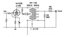
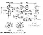
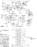
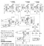
Thank you both for your continued valuable input. Please refer to Post #104 in this thread. Note the schematic which is on the far right. This amp uses a combination of positive and negative feedback.
The output impedance of this amp is expected to be low. I am guessing a conservative positive impedance of 100 milliOhms. Thus, it has a damping factor [in 8 Ohm loudspeaker] equal to 8 Ohms divided by 0.1 Ohm = 80.
Best
Anton
Hi Anton,
the amplifier in #104 you've been referring to doesn't feature that kind of feedback that I've meant. Those from the 1950ies have a current sensing resistor (shunt) between the OT secondary's gnd end and gnd. Across this is a trimpot. The NFB low resistor's gnd end is connected to this pot's wiper.
Best regards!
Hi Anton,
the amplifier in #104 you've been referring to doesn't feature that kind of feedback that I've meant. Those from the 1950ies have a current sensing resistor (shunt) between the OT secondary's gnd end and gnd. Across this is a trimpot. The NFB low resistor's gnd end is connected to this pot's wiper.
Best regards!
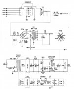
The electrovoice circlotrons had this feature of both voltage and current feedback ... R5 2.7 ohm is the current sense pot.
http://circlotron.tripod.com/a50.pdf
Last edited:
The electrovoice circlotrons had this feature of both voltage and current feedback ... R5 2.7 ohm is the current sense pot.
http://circlotron.tripod.com/a50.pdf
Hello Sorento. Thank you for the above link and its interesting schematic. I have experimented with Positive Current Feedback [PCF] using solid state amps, and had fun doing so. My time to study the circlotron schematic!
Best
Anton
The electrovoice circlotrons had this feature of both voltage and current feedback ... R5 2.7 ohm is the current sense pot.
http://circlotron.tripod.com/a50.pdf
Yes, but these also were 1950ies designs - as I said before
.Best regards!
- Home
- Amplifiers
- Tubes / Valves
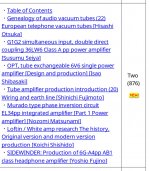
- Gold mine of DI¥ audio tubes schematics from Japan