seems more realistic to me....or a 5:1 ratio....
Indeed. With 33:1 and just 110H perfomance will change like night and day from midrange to low frequency.
Audio Note, since it was sold to Qvortrup, has been producing good things but also garbage.....nothing to do with the original anyway except for those items that have remained unchanged or nearly unchanged.
If they changed it means that it was not good enough. Don't you think? Now they have made soething not too different but I wouldn't say better...Why are you guys still fussing around with the ratios? Qvortrup already disclosed how AN did it, whether you like it or not, iiwis... the turns ratio is 33:1 unbalanced.
But not sure where the 110H primary inductance came from....
It's in one of the links you or others provided. However I doubt that one will ever get enough inductance for 650K primary impedance. 300H wouldn't be enough anyway.....assuming it can still pass enough DC current with decent losses.
Balanced or unbalanced would not change a lot. Balanced would be 1/2 of that disproportionate ratio. Still too high....for 600R load.
Any help with the sim?
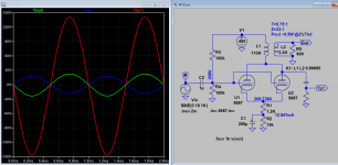
T=5.75:1
Z=33:1
Pout ~0.5W @2%Thd
That's over 17V rms into 600R. Are you really going to drive a power amp that is that bad?
Your result is also high distortion because you run each triode of the 5687 at 6.5 mA only....not really linear. The primary swing for 0.5W output is about 280V peak-to-peak.
Last edited:
No, you are jumping to conclusion... anyway, the OP did not really ask how good/bad the AN transformers were, only how he could wind one himself for his diy project, that's all...If they changed it means that it was not good enough. Don't you think? Now they have made soething not too different but I wouldn't say better...
The output transformer is 33:1 turns ratio, which seems OK as the gain of the line amplifier (6072 SRPP cascaded to paralelled 5687) is more than 300.
Checking the schematic, loading the output stage with 600 ohm is optional .
Source impedance for the output transformer is some 1 k (parallel 5687).
Loading with 600 ohm or not, a primary inductance of some 40 H would have been sufficient.
Checking the schematic, loading the output stage with 600 ohm is optional .
Source impedance for the output transformer is some 1 k (parallel 5687).
Loading with 600 ohm or not, a primary inductance of some 40 H would have been sufficient.
The output transformer is 33:1 turns ratio, which seems OK as the gain of the line amplifier (6072 SRPP cascaded to paralelled 5687) is more than 300.
Checking the schematic, loading the output stage with 600 ohm is optional .
Source impedance for the output transformer is some 1 k (parallel 5687).
Loading with 600 ohm or not, a primary inductance of some 40 H would have been sufficient.
Nice recipe for high distortion at low frequency. Already at 100Hz....
Last edited:
Perfectly ok?
The transformer is made to work with about 10 mA anode current, and so the maximum PRIMARY swing it can do at 20Hz with just 40H (and that means the tube is about to cut off) is 35.5V RMS. If the turn ratio is 33:1 it means that maximun output is just over 1 V RMS with a lot of distortion! Likely double digit.
The transformer is made to work with about 10 mA anode current, and so the maximum PRIMARY swing it can do at 20Hz with just 40H (and that means the tube is about to cut off) is 35.5V RMS. If the turn ratio is 33:1 it means that maximun output is just over 1 V RMS with a lot of distortion! Likely double digit.
No, you are jumping to conclusion... anyway, the OP did not really ask how good/bad the AN transformers were, only how he could wind one himself for his diy project, that's all...
That transformer might only work acceptably if you have another identical in step-up mode at the input of the power amp. Otherwise it is a waste of time and money. That's all....
Perfectly ok?
The transformer is made to work with about 10 mA anode current, and so the maximum PRIMARY swing it can do at 20Hz with just 40H (and that means the tube is about to cut off) is 35.5V RMS. If the turn ratio is 33:1 it means that maximun output is just over 1 V RMS with a lot of distortion! Likely double digit.
40H is enough primary inductance for a parallel 5687 in a normal line stage.
The output stage of that M10 is a bad design; apparently all Audionote designs from that period had to contain the "magical" SRPP.
The huge amount of voltage gain in the M10 output stage had to be transformed down by the huge 33:1 step down ratio: what a waste....
The 5687 in the M10 will distort already because of too high input voltage (with let's say 0.5 VRMS from the phono stage the grids of the 5687 must take over 10 VRMS which they can not without severe distortion, no matter primary inductance...).
Skipping the 6072 SRPP, and using a 3:1 output transformer for the 5687 would change the M10 design into a much better one
") .
.I don't know it. I am only talking about the output transformer. The whole M10 schematics is not necessary to assess the transformer. Only the output stage.
If the output stage works with 10 mA anode current and the turn ratio is 33:1 then it is not good for generic use even if the rest of the preamp were the best in the world.
Such an output stage would only work decently (because distortion at low frequency will never be as good as a no-transformer preamp) if used with a high step-up transformer at the input of the power amp. But then that not would be a power amp but rather a booster!
Indeed. With 33:1 and just 110H perfomance will change like night and day from midrange to low frequency.
Audio Note, since it was sold to Qvortrup, has been producing good things but also garbage.....nothing to do with the original anyway except for those items that have remained unchanged or nearly unchanged.
a friend showed me a box of Sowter, 15k to 600 ohm IT, have you tried those? anyone?
unfortunately, he passes and i do not know what happened to them, there are at least 10 pcs of those in that box....
I don't know them Tony, sorry. If you know the model at least we could try to speculate. However 15K-to-600K for a line output transformer can be good if the other specs are right.
The only signal transformer made by Sowter I know is the 9063. Used as input transformer for a power amp in 1:4 or 1:2 mode in SE or 1:2+2 as a PP splitter and driven by a capable OTL/OCL preamp this is excellent.
The only signal transformer made by Sowter I know is the 9063. Used as input transformer for a power amp in 1:4 or 1:2 mode in SE or 1:2+2 as a PP splitter and driven by a capable OTL/OCL preamp this is excellent.
You are using a turn step-down ratio of 5:1 and not 33:1 as someone is dreaming of.....
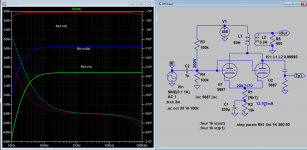
What if you use a 33:1 step-down ratio? What is the max undistorted output voltage at 20 Hz?
There is no need to run simulations. The max primary voltage (sinusoidal regime) a tube running at 10 mA can give into 40 and 60H is 4.44*L*Idc*f. So this is 35.5 and 53.3 V rms, respectively. However this is the absolute max and will be affected by a lot of distortion because the tube is not really linear over the whole range. Then step-down by 33:1 and you get 1.07 and 1.61 V rms, respectively. In practice it is even less because of losses!
I don't know it. I am only talking about the output transformer. The whole M10 schematics is not necessary to assess the transformer. Only the output stage.
If the output stage works with 10 mA anode current and the turn ratio is 33:1 then it is not good for generic use even if the rest of the preamp were the best in the world.
I meant the output stage.
Creating a gain of more than 300 with two stages, and transforming that down with a high ratio step down transformer.....
When power supply voltage is around 300V, and anode current of the 5687 is 10 mA, the tube can have some 5 VRMS on its grids.
Gain will be about 18 with an unloaded secondary, so, combined with a 33:1 output transformer, undistorted output voltage is less than 3 VRMS, and that is accomplished with two gain stages
Horrible design!!The phono stage might be good, no idea.
- Status
- This old topic is closed. If you want to reopen this topic, contact a moderator using the "Report Post" button.
- Home
- Amplifiers
- Tubes / Valves
- Audio Note M10 Clone