I finally defeated my laziness and decided to write a short Audion Edison 60 building report:
Edison 60 prices and options
I have got all the available options (incl. tantalum and foil capacitors), but not the silver wire. The variant built here is the Edison 60 plus dual monoblock 30W push-pull Class A amp, with the Silver Night output transformers. As a short background, I am an Electrical/Software engineer, with limited background in High Voltage (think >30.000V) applications, and significant experience in low voltage (48-1200V) region.
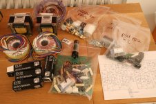
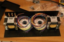
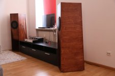
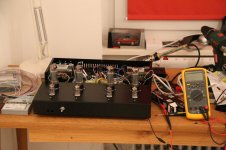
The kit was delivered excellently packed, in just a few days after placing the order. I found it impressive that the output trafos were wound and baked after the order was placed. This configuration, as seen in the pictures did require some careful planning and hole drilling, in order to allow a symmetrical transformer arrangement.
Although this was not my first build, it took me a significant number of days to finish it. I do take a lot of pleasure in working slowly and to perfection, while anticipating the final result. The kit does offer a lot of satisfaction from this point of view.
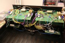
As seen in the pictures, the "Plus" kit comes with two power supply toroids+boards. The amp itself is a hybrid between point-to-point and board soldered constructions. The soldering itself is not particularly challenging, with parts this size.
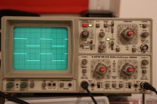
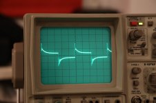
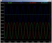
The oscilloscope screen shots show the square wave response during the amp's burn-in process (after 2 minutes from the first power up, capacitors not yet polarized, after 50 hours and finally settled after 100 hours). Any questions, comments, suggestions, etc, are welcome") .
.
Edison 60 prices and options
I have got all the available options (incl. tantalum and foil capacitors), but not the silver wire. The variant built here is the Edison 60 plus dual monoblock 30W push-pull Class A amp, with the Silver Night output transformers. As a short background, I am an Electrical/Software engineer, with limited background in High Voltage (think >30.000V) applications, and significant experience in low voltage (48-1200V) region.
The kit was delivered excellently packed, in just a few days after placing the order. I found it impressive that the output trafos were wound and baked after the order was placed. This configuration, as seen in the pictures did require some careful planning and hole drilling, in order to allow a symmetrical transformer arrangement.
Although this was not my first build, it took me a significant number of days to finish it. I do take a lot of pleasure in working slowly and to perfection, while anticipating the final result. The kit does offer a lot of satisfaction from this point of view.
As seen in the pictures, the "Plus" kit comes with two power supply toroids+boards. The amp itself is a hybrid between point-to-point and board soldered constructions. The soldering itself is not particularly challenging, with parts this size.
The oscilloscope screen shots show the square wave response during the amp's burn-in process (after 2 minutes from the first power up, capacitors not yet polarized, after 50 hours and finally settled after 100 hours). Any questions, comments, suggestions, etc, are welcome
.Attachments
-
 14372368_10207398091526827_1055582504439404550_o.jpg231.3 KB · Views: 1,386
 -
 14425402_10207421939763018_4103438343659090343_o.jpg126.7 KB · Views: 1,295
 -
 14435348_10207421942003074_1515051253629871555_o.jpg193 KB · Views: 1,336
 -
 14434913_10207416730672794_1759579714657112955_o.jpg251.9 KB · Views: 1,236
 -
 20157625_10209803225773680_6418597749122841262_o.jpg142.1 KB · Views: 609
 -
 After 100 hours.JPG216.9 KB · Views: 487
 -
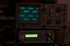 After 50 hours.JPG104.9 KB · Views: 434
 -
 Afte 2 minutes.JPG114.7 KB · Views: 664
 -
 14633143_10207536531947751_7050140951142496690_o.jpg181.3 KB · Views: 1,294
 -
 14543826_10207536487786647_5717478435651052394_o.jpg230.8 KB · Views: 784
Last edited:
Oh, BTW, sound-wise, this is probably the best 30W amp one can get period. I'm using it with 98dBmW FE206En speakers (usually <1W, but sometimes at a very loud 15W of power), and the bass-mids-high dynamics, stage presentation and (lack of) noise is better than anything I've ever heard before. Can't imagine this being significantly improved by another amp, for sure.
A lot of hyperbole here, but as long as you like it, that's all it matters.
The oscilloscope screen shots show the 1kHz square wave response during the amp's burn-in process (after 2 minutes from the first power up, capacitors not yet polarized, after 50 hours and finally settled after 100 hours).
Are there electrolytic caps in the signal path?
… 98dBmW FE206En speakers...
More like 96 dB.
30W seems a bit optimistic for a pr of EL34 in Class A.
dave
You can check easily the class if you put a 1 ohm 1 watt resistor in series to each cathode of the EL34 to ground.
With the scope you can see the wave; if it is 360° you are in class A.
When one half becoming "compressed" you are moving to class AB. On load you can read the value of V.
Walter
With the scope you can see the wave; if it is 360° you are in class A.
When one half becoming "compressed" you are moving to class AB. On load you can read the value of V.
Walter
>Are there electrolytic caps in the signal path?
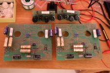
LOL, nope, of course not. You can see the four big golden ERO foil capacitors in the pictures. Those are the signal caps (1000V .33uF). They do polarize with usage, and the process takes about 100 hours, as seen on the scope traces.
>Did you verify that the amp was still in Class A at clipping?
Vpq is less than 60% of B+ at 30W, but honestly I didn't do any deeper measurements, as I'm using it mostly under 1W, usually. Presuming it stays in Class A over the range (I still have the scope trace screenshots at 30W, but the class can't be seen from there).
Their specs also mention pure Class A @30W also, and I've found their specs to be very accurate.
The Audion Silver Night output transformers are for up to 50W.
98dB - for sure it's because of my room's reflection. I don't doubt the speaker's 96 dB spec or your measurement.
>Looks like the whole kit is straight from the 80's! I can't believe they still have all that left in stock after all this time.
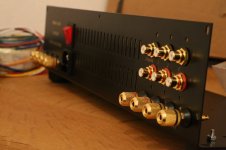
Yep well, it's a tube amp, in the typical British design. WAF is very high on this one, basically it looks good with the mirrored stainless steel.
I don't quite understand the negativity here. I'm posting a tube amp building report on a freaking tube amp DIY forum...
LOL, nope, of course not. You can see the four big golden ERO foil capacitors in the pictures. Those are the signal caps (1000V .33uF). They do polarize with usage, and the process takes about 100 hours, as seen on the scope traces.
>Did you verify that the amp was still in Class A at clipping?
Vpq is less than 60% of B+ at 30W, but honestly I didn't do any deeper measurements, as I'm using it mostly under 1W, usually. Presuming it stays in Class A over the range (I still have the scope trace screenshots at 30W, but the class can't be seen from there).
Their specs also mention pure Class A @30W also, and I've found their specs to be very accurate.
The Audion Silver Night output transformers are for up to 50W.
98dB - for sure it's because of my room's reflection. I don't doubt the speaker's 96 dB spec or your measurement.
>Looks like the whole kit is straight from the 80's!
I can't believe they still have all that left in stock after all this time. Yep
well, it's a tube amp, in the typical British design. WAF is very high on this one, basically it looks good with the mirrored stainless steel. I don't quite understand the negativity here. I'm posting a tube amp building report on a freaking tube amp DIY forum...
>You can check easily the class if you put a 1 ohm 1 watt resistor in series to each cathode of the EL34 to ground.
Indeed, haven't done that. All the other measurements I've done (and their specs) show pure class A over the power range, and given their quality, I have no reason to doubt that, really
Indeed, haven't done that. All the other measurements I've done (and their specs) show pure class A over the power range, and given their quality, I have no reason to doubt that, really
Days? Not bad. I like working like this, well, super slow actually, enjoy most the planning, the doing can be a bit tedious as I've already done it in my headAlthough this was not my first build, it took me a significant number of days to finish it. I do take a lot of pleasure in working slowly and to perfection, while anticipating the final result. The kit does offer a lot of satisfaction from this point of view.
The proviso is that I have a functioning amp to listen to in the mean time of course>When you have the electrolytic (or other types) on power supply they are on signal path
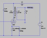
Well, nope, the audio signal does never pass through the power supply caps, so they are not in the signal path. That's the commonly accepted definition. They do contribute to the final signal, true, The signal capacitors are the C1, C2, C10, C13 - the big golden ELO MKT1813 1000V .33uF ones in the pictures.
Also with Vpq is significantly less than B+, the amp is in pure class A (this I measured).
Here is the schematic, btw... With autobias.
Attachments
Last edited:
...so they are not in the signal path. That's the commonly accepted definition.
I and LTSpice would quibble strongly with that definition, but rather than start another endless debate just wanted to point out craft stores catering to jewellers carry 99.98% pure dead soft bare silver wire in gauges suitable for hookup for under $1/foot. It's cheap to try out. Higher purity is reportedly almost always NASA grade unobtanium or marketing fiction.
Well, what's the definition then? Original audio signal does not pass through the power supply caps, so they aren't in the "signal path". The output audio signal does pass through the power supply, so the electrolytic caps will influence the final output. Given the lack of noise, even with 96dB speakers, and even at very loud volume, there is no problem with the electrolytics there.
>but rather than start another endless debate just wanted to point out craft stores catering to jewellers carry 99.98% pure dead soft bare silver wire in gauges suitable for hookup for under $1/foot.
- I stayed with good old copper, although I did install the tantalum resistors. I care not about tantalum, but they're made with audio in mind, and the tolerances were the tightest I ever measured (all were between 0.9999 and 1.0001 Ohm). I don't think silver offers a significant advantage over copper, though.
Last edited:
Original audio signal does not pass through the power supply caps, so they aren't in the "signal path".
I rarely sweat definitions, almost always too much social and linguistic noise. Rather just look at circuit behaviour. Call them whatever you like, what really matters is dynamic audio current passing through the plate load is mirrored in the power supply and cathode caps. Below is a simple circuit thrown together to illustrate with sim results. Large dynamic audio currents flow everywhere, ironically least of all through the cathode bias resistor.
Looked at in the simple terms of, for lack of better label, 'introduced error' the PS cap would inject them in the least sensitive part of the circuit but it's also the greatest voltage swing. Potential cathode cap 'introduced error' directly effects the grid-cathode voltage and would be amplified.
Viewed from that perspective I never found it useful to define them as not in the signal path.
Attachments
- Status
- This old topic is closed. If you want to reopen this topic, contact a moderator using the "Report Post" button.
- Home
- Amplifiers
- Tubes / Valves
- Audion Edison 60 building and using report