Hello to All,
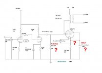
I need your help with a schematics I found in the net. I am interested in an easy 813 SE Amp. I found a schematics from Richard Ellis, but I found no further information. I think, this schematics have some "Faults". But I am not 100% sure.
Here is the schematics, I hope, I will get some feedback from some experts.
Thank you.
Attachments
See 813 final design?
There is no fault... Also you can't use a 1M grid resistor on the 813, 200k is about as high as you can go, but 50k works just fine.
There is no fault... Also you can't use a 1M grid resistor on the 813, 200k is about as high as you can go, but 50k works just fine.
That pertains to class AB and B operation, but even with cathode bias, it's still a good idea to keep the grid resistor as small as possible.Kathode bias is not recommended according to the datasheet though.
G2 is rated for 1100V, AF pentode operation.
Triode mode often allows even higher G2 voltages.
Kathode bias is not recommended according to the datasheet though.
The tube is rigged 43% U-L. You are going to need more than 900V on the g2 to start with. Or g1 positive drive. Or an impractically high load.
Also, hunting for acceptable schematics on the web requires you to know that you have a good one or not. Otherwise you might as go look for proof of conspiracies.
cheers,
Douglas
Last edited:
Question Power Supply 813 SE Amp
Hi to All,
I have a question about an idea about the power supply for my new 813 SE Amp project.
The power supply provide the 900V HT for the 813 tube. The power for the driver tube, I like to take from the first capacitor of the power supply.
The driver tube 6SN7 take only around 2mA, so I think, I could take it from the first capacitor, approx. 300V. I am right, or this is not possible.
Please see attached picture. I like to keep this amp as easy as possible. Hope to get an answer, thank you.
Attachments
> I think, I could take it from the first capacitor, approx. 300V.
No. The current would have to come from the string of 390K resistors. Even 1mA load would sag it to near Zero. Your 300V demand is far more than 1mA (nearer 10mA).
This probably wants another transformer, 240VAC, to make the 300+V DC supply.
A dropping resistor from 900V would work when all was hot, but would put full 900+V on the little parts at cold-start.
A pass-tube could drop the voltage, but needs another heater transformer. A MOSFET could drop it, but at 900+V you are at the upper end of available MOSFETs(?).
Redrawn Schematics 813 SE Amp Richards Ellis
I have redrawn the schematics from the 813 SE Amp from Richards Ellis. I hope, there is no fault inside. Is it better to use a negative Grid voltage for Grid 1 from the 813 tube? Some amps use -100 to -110 volts. Could some please advice.
Thank you.
I have redrawn the schematics from the 813 SE Amp from Richards Ellis. I hope, there is no fault inside. Is it better to use a negative Grid voltage for Grid 1 from the 813 tube? Some amps use -100 to -110 volts. Could some please advice.
Thank you.
Attachments
Hi audiowize,
thanks for the comment, but I am not that advanced like you. Could you tell me how to do the feedback from OPT to 6SN7 tube. I just start to build this amp.
First, I use the schematic from Mr. Willis with 6J5GT ( half 6SN7) tube. Not much power output. I will replace the 6SN7 with the ECC40 tube. The ECC40 is same like 6SN7 but less microphonic. Or do you have a better schematics for 813?
Thank you.
The 6SN7 isn't going to be a good choice for plate to plate feedback, so I guess that leaves a CFB winding?
I see no reason to use a 6SN7 here.
As far as 'another circuit' goes, that is not so difficult at all...
") it is just a PP to SE conversion of my 813 amps I have been running since 2007.
it is just a PP to SE conversion of my 813 amps I have been running since 2007.cheers,
Dogulas
How can you bias the cathode, when the heater is the cathode?That pertains to class AB and B operation, but even with cathode bias, it's still a good idea to keep the grid resistor as small as possible.
Floating filament power supplyHow can you bias the cathode, when the heater is the cathode?
- Home
- Amplifiers
- Tubes / Valves
- Schematics 813 SE Amp Richards Ellis