Wanted to pass on some experimentation results here.
So I have built a KT88 PP UL using Williamson topology, 12AX7 gain/splitter, 12AU7 drivers (don't flame me for this choice please, I appreciate not everyone agrees with these tubes, but it works and tests well).
Output iron is Hammond 1650R.
In tuning the GNFB, I have used the method recommended by Morgan Jones (pp. 290-291 "Building Valve Amplifiers" 4th. Ed) and I found that without any compensation, the ringing was indeed quite unacceptable. Then I put the capacitor across the feedback resistor and watched the ringing decrease to practically zero.
Thinking I'd gotten away without having to put any compensation on the load resistor, I put a 220nF cap across the speaker terminals as recommended, and watched the output go absolutely crazy.
Then I continued the recommended procedure and put the capacitor across the load resistor, and it didn't do much (or anything at all) to the output into the straight resistive load, but putting the 220nF across the output once more had almost no effect.
So from my own observation, based on a sample size of one, very inexpertly (as I have been often told!) built amplifier, empirical observation suggests that capacitors across anode load resistors in the initial gain stage greatly stabilize the amplifier into a capacitive load.
Oscillosope traces etc are here for those interested
-- Standard Disclaimer --
If this post is not appropriate or offends someone please PM me and I'll remove it
If this post is not appropriate or offends someone please PM me and I'll remove it
So I have built a KT88 PP UL using Williamson topology, 12AX7 gain/splitter, 12AU7 drivers (don't flame me for this choice please, I appreciate not everyone agrees with these tubes, but it works and tests well).
Output iron is Hammond 1650R.
In tuning the GNFB, I have used the method recommended by Morgan Jones (pp. 290-291 "Building Valve Amplifiers" 4th. Ed) and I found that without any compensation, the ringing was indeed quite unacceptable. Then I put the capacitor across the feedback resistor and watched the ringing decrease to practically zero.
Thinking I'd gotten away without having to put any compensation on the load resistor, I put a 220nF cap across the speaker terminals as recommended, and watched the output go absolutely crazy.
Then I continued the recommended procedure and put the capacitor across the load resistor, and it didn't do much (or anything at all) to the output into the straight resistive load, but putting the 220nF across the output once more had almost no effect.
So from my own observation, based on a sample size of one, very inexpertly (as I have been often told!) built amplifier, empirical observation suggests that capacitors across anode load resistors in the initial gain stage greatly stabilize the amplifier into a capacitive load.
Oscillosope traces etc are here for those interested
capacitors across anode load resistors in the initial gain stage greatly stabilize
the amplifier into a capacitive load.
This reduces the open loop bandwidth by adding a dominate hf pole, until stability is achieved
when closing the loop with worst case loading. Such lag compensation has been standard practice
in many tube amplifiers.
Last edited:
Yup lead and lag compensation with any amp using a healthy amount of feedback does wonders for stability.
Amplifier Compensation.
Amplifier Compensation.
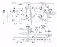
I've built an amp some years ago -see schematic- and at some point I thought to change the power section from pentode to triode connection and remove nfb just from curiosity. I realized that I lost low and high frequencies doing so. Things improved when I increaced the value of the coupling caps to the output stage and removed the 100pf/20k circuit in parallel with the load resistor of the EF86. So, I guess these go together with nfb.
Attachments
Aros71,
You have 'discovered' only two elements of NFB theory. The complete theory consists of many more elements, and I suggest that you google some reference to basic NFB techniques before going on. (I am not lazy to help you here, but any complete theory will take several screenfuls of text + diagrams. Not too involved, just several basic elements.)
Still, very briefly (thus incomplete), it has to do with balancing phase shifts (called 'poles') within a feedback loop so as to keep negative feedback negative and avoiding oscillation. A large capacitance across the output might often cause this. Such is not necessary; one can get no circuit absolutely stable under all conditions. One stays with what is practical, the rest is unlikely to occur.
One aspect of 'the rest' is a large capacitance across the output. The most to design for there is a practical value for cable capacitance; 220nF is far to high to ever happen there.
The 100 pF and 20K is as mentioned a step measure, again to compensate for h.f. poles elsewhere. In an optimal design they should not cut into the audio range, but such is unfortunately often the case.
But I have another point: The 0,47µF screen bypass for the input EF86 should go to the tube's cathode, not earth. (True pentode operation is only realised with screen and cathode signal potential the same, otherwise one gets a resultant signal on the screen and is the operation affected.) When there is a large feedback signal on the cathode - often some 10-fold the input signal, the connection as shown can have consequences. (In the equivalent diagram one is putting a large signal between cathode and screen. That is no longer basic pentode operation. I fear you will notice this kind of screen bypass in several tube power amps, probably as a habit to 'bypass the screen' to earth, in cases where the cathode is also at earth signal potential. Here it is not.)
See where the length went - and I have not even started! Google is your friend to illustrate NFB basics!
Did somebody say stability? ") Look at Stu Hegeman's H/K Cit. 2. It's unconditionally stable.
Look at Stu Hegeman's H/K Cit. 2. It's unconditionally stable.
Look at Stu Hegeman's H/K Cit. 2. It's unconditionally stable.Aros71,
The 0,47µF screen bypass for the input EF86 should go to the tube's cathode, not earth....
Cool- thanks for your useful reply. Just a note though - that EF86 schemo you referenced isn't mine, I can't take the credit for that! That's MagicBus' work. If you want to see my one, click the blog link below, the most recent post has the latest circuit schematic.
- Status
- This old topic is closed. If you want to reopen this topic, contact a moderator using the "Report Post" button.
- Home
- Amplifiers
- Tubes / Valves
- Stability into capacitive loads