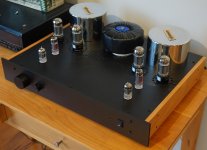
Just completed amp using 7591a valves and Toroidy transformers from Poland. Very happy with the performance of these transformers and their modest price.
(Cathode Feedback). Amp sounds a good as my last attempt using Hashimoto output transformers. Power bandwidth (22 watts) from 20hz to 75khz.
GregT
(Cathode Feedback). Amp sounds a good as my last attempt using Hashimoto output transformers. Power bandwidth (22 watts) from 20hz to 75khz.
GregT
Attachments
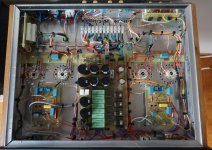
Transformers
The output are TTG-EL34PP EXPO 6K6 Plate to plate and 30% UL and 10% CFB.
The mains transformer I wound by hand and is still to have its cover. See image
The Powersupply is shown on new schematic below. Just shown is the ECC83 and ECC99 power supply. The ECC83 has DC for Heaters.
GregT
The output are TTG-EL34PP EXPO 6K6 Plate to plate and 30% UL and 10% CFB.
The mains transformer I wound by hand and is still to have its cover. See image
The Powersupply is shown on new schematic below. Just shown is the ECC83 and ECC99 power supply. The ECC83 has DC for Heaters.
GregT
Attachments
Transformers
Yes the transformer is the TTG-CFB6600PP model. I think I stated that it was the TTG-6600PP Expo model. Sorry for the mixup.
The only issue I had during assembly was with the CFB windings being poorly marked and this required checking on the scope before deploying the CFB windings.
The use of CFB requires the driver stage to delivery approximately twice the voltage drive to the output tubes. Hence the use of the 7591A. This tube is easily driven compared to many other output tubes, hence less stress on the ECC99 driver.
The use of CFB requires the driver stage to delivery approximately twice the voltage drive to the output tubes. Hence the use of the 7591A. This tube is easily driven compared to many other output tubes, hence less stress on the ECC99 driver.
It might be twice in your case but it's not a rule. The required swing is the normal swing + the voltage that will be developed at the cathode of the output tube. So if 10% of the turns (of the total anode + cathode turns) are at the cathode then the additional swing will be 10% the output voltage.
Thanks 45. Yes I should have stated that this "twice" is specific to this design.
This is the first amp I have designed and built using CFB and I have to say I like the sound. Even more impressive was the price of these transformers being about a third of that spent on the Hashimoto's I have used in the past. Certainly the Hashimoto is a premium transformer (and sounds great) but the cost including freight to New Zealand makes them very expensive. My 66 year old ears cannot hear any significant difference between these two transformers.....no doubt younger ears may pick up small differences
This is the first amp I have designed and built using CFB and I have to say I like the sound. Even more impressive was the price of these transformers being about a third of that spent on the Hashimoto's I have used in the past. Certainly the Hashimoto is a premium transformer (and sounds great) but the cost including freight to New Zealand makes them very expensive. My 66 year old ears cannot hear any significant difference between these two transformers.....no doubt younger ears may pick up small differences
Measured with GFB. I'm looking to redesign the input stage. I noticed a mistake in my calculations re the ECC83, and although it does not seem to effect performance I will still re-design this stage. The current amp is stable into a 1uf and 8ohm load but a redesigned front end should further help with stablity margin. Will also check bandwidth without GFB and may reduce GFB.
I have had a look at the specs and they are a bit odd. They quote 10% Ra for cbf which should be about 24% in terms of cathode turns over total plate + cathode turns. That's quite a lot considering the UL tap. However the 33% UL connection makes me think that 10% is referred to turns....
The 10% CFB and 30% Ultralinear Taps is pretty standard configuration for output trannies. Recall that UL feedback to the screen is screen to cathode voltage so with the 10% cathode feedback then you effectively have 10 + 30 = 40 % Ultralinear, the "standard-ish" UL ratio. I have a pair of these on the shelf for a new pair of HiFi Monoblocks: https://www.plitron.com/wp-content/uploads/2010/05/2100CFBH.pdf Note that they are very similar impedance ratios, 10% cathode feedback windings and 33% screen tap to give 43% Ultralinear plus the cathode feedback. These will have a quad of Gold Lion re-issue KT88 to drive them. Probably use ECC99 drivers too unless I go "brute force and ignorance" path with a pair of triode strapped 6V6 or EL84 as drivers. Cheers, Ian
This is great. Is it possible to note on the schematic the colors of the wires for those of us that want to use these transformers and save us time figuring out which windings are which, thanks!
The transformer comes with good colour coding (easy to follow) with the exception of the two CFB windings. They are Pink (2 wires) and Purple (two wires). Although one of each has a black band, it was still necessary to check on scope to get this right. If I was to place another order then I would ask them to better code these.
Probably use ECC99 drivers too unless I go "brute force and ignorance" path with a pair of triode strapped 6V6 or EL84 as drivers.
Cheers,
Ian
The ECC99 seem to drive output very well. With the Current source in the tail I had an AC balance at better than 0.5% The only change I would recommend (just for safety) would be to use high voltage transistors.
I'm changing the first stage to reduce the output impedance of this stage. It should help (in theory) with stability, although the current amp is stable into a 1uf and 8 ohm load. I will reduce the load on the paralleled ECC83 down to 25k5 and the two cathode bias resisters to 200 and 100 ohms. This will drop the output impedance to 18K and allow for a better driving of the ECC99. I did consider using an ECC88 for the first stage but wanted the extra gain of the ECC83. Will re-post schematic when I have completed change.
- Status
- This old topic is closed. If you want to reopen this topic, contact a moderator using the "Report Post" button.
- Home
- Amplifiers
- Tubes / Valves
- PP amp with Toriody Transformers and 7591A