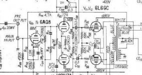
The 10% CFB and 30% Ultralinear Taps is pretty standard configuration for output trannies.
Recall that UL feedback to the screen is screen to cathode voltage so with the 10% cathode feedback then you effectively have 10 + 30 = 40 % Ultralinear, the "standard-ish" UL ratio.
I have a pair of these on the shelf for a new pair of HiFi Monoblocks:
https://www.plitron.com/wp-content/uploads/2010/05/2100CFBH.pdf
Note that they are very similar impedance ratios, 10% cathode feedback windings and 33% screen tap to give 43% Ultralinear plus the cathode feedback.
I know how transformers work, what Plitron does and that in general percentages are referred to turns. I make my own transformers.
However Toroidy state that the cfb winding is 10% Ra. There is quite some difference and is an alternative definition. The fact that UL tap is at 33% makes me think of a mistake but I do not trust merchants...

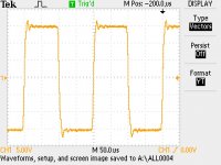
Some images of output
I note that their has been some negative comment on Toroidy transformers. I have found their PP transformers to be fine. Not as good as the Hashimoto I have used previously but still very good when considering the price.
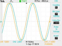
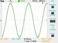
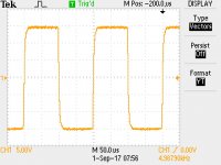
The first image is of 5khz square wave into 8 ohm resistor. The second is into 8 ohms and 1 uf at same frequence. Third is sine wave both input and output (into 8 + 1uf). Final is 21 hz into 8 + 1uf.
Greg
I note that their has been some negative comment on Toroidy transformers. I have found their PP transformers to be fine. Not as good as the Hashimoto I have used previously but still very good when considering the price.
The first image is of 5khz square wave into 8 ohm resistor. The second is into 8 ohms and 1 uf at same frequence. Third is sine wave both input and output (into 8 + 1uf). Final is 21 hz into 8 + 1uf.
Greg
Attachments
Changes to 7591A amp
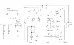
Yes. I have made a lot of changes. Not that they were needed but I'm always keen to experiment. The changes increase/improve the phase margin for better stability (Design concept taken from a Norman Koren amp). The changes sound better in my view. New schematic attached. The Frequency response and waveforms are very similar to above (indistinguishable) so just posted the amp circuit. 20 watts output with 400Volts supply. This new circuit has greater local feedback and no global feedback. (Feedback loop from output to driver stage only).
Toriody are always helpful so if ordering the transformers, you could ask to have a centre tap on the output transformer. I.e. instead of a 0,4,8-ohm output get then to provide a 0-8 ohm with a centre tap (Note that 4 ohms is not a centre tap). This would negate the need for the two 56ohm 5-watt resistors to create a virtual centre tap on the speaker output. Happy to provide any help with your build. I do have PCB designs for the gain and driver stage.
Cheers
Attachments
Having two feedback paths from the output transformer secondary requires that both speaker outputs are isolated from ground. This does create some minor issues both from an assembly and safety perspective. I used a piece of PCB (fully etched) to mount the speaker terminals to ensure they were isolated from the chassis.
It would be best to get Toriody to provide a centre taps for the 8 ohm secondary. This means that the secondary is directly attached to ground, and is preferable in the unlikely instance of a fault causing HT to break through the transformer into the secondary winding
Alternatively the 4ohm winding could be earthed and the two feedback paths could be adjusted to ensure that same level of feedback (I did calculate valves for this approach.)
But I kept it simple and use two 56ohm from the two 8 ohm taps and earthed the centre of the resistors. This does mean that the output secondary is connected to earth through 2 x 56ohms 5 watt. Not as good/safe as the above options but given the presence of fuses both in the HT supply and plate fuseable resistors its ok....but option one above is my recommendation
Thanks for the info. I'm going to try and make these transformers, the TTG-CFB6600PP work with 7591a's and the baby huey el34 pcb boards in another thread.
Since the boards will drive el34's I'm hoping to drive 7591a's even considering the extra drive required with cathode feedback.
Thanks also for demonstrating 7591a's can be run in ultra linear. Finding evidence of this capability other than on the data sheet is nearly impossible.
Since the boards will drive el34's I'm hoping to drive 7591a's even considering the extra drive required with cathode feedback.
Thanks also for demonstrating 7591a's can be run in ultra linear. Finding evidence of this capability other than on the data sheet is nearly impossible.
Last edited:
Power supply
Minor changes to power supply see attachment. The 6N1P driver tube is designed for a max Plate voltage of 250 to 300 Volts. A simple Resistor/Capacitor power supply for the 6N1P would have see as much as 420 volts on warm-up. Way to much. The use of the MOSFET regulators (Taken from Norman Korens design) ensures that this warm-up voltage limits this over-voltage and reduces the need for Electrolytic Capacitors. But this all makes the power supply rather more complex.
Minor changes to power supply see attachment. The 6N1P driver tube is designed for a max Plate voltage of 250 to 300 Volts. A simple Resistor/Capacitor power supply for the 6N1P would have see as much as 420 volts on warm-up. Way to much. The use of the MOSFET regulators (Taken from Norman Korens design) ensures that this warm-up voltage limits this over-voltage and reduces the need for Electrolytic Capacitors. But this all makes the power supply rather more complex.
Attachments
You are right, these MOSFETs are not in the pure sense regulators, rather Capacitor Multipliers. But the resistor Divider 220k and 560K leading to the gate of the MOSFET for the 280volt supply to the 6N1P ensures that the voltage, even on turn-on, does not get too high. A simple Resistor/Capacitor network would have seen 420 volts on the Plate of the 6N1P on turnon
Thanks
Thanks
Last edited:
Two 6.3 volt AC windings for each channel. The output tubes share with the 6N1P. Each 6.3 AC volt winding has a centre tap that is earthed. The 4 X 10,000uf are needed to ensure low ripple on the 12.6 DC supply. The circuit as show has about 10 millivolts of hum (measured). Capacitors were available in junk bin so I used this approach rather than a 12Volt regulator.
- Status
- This old topic is closed. If you want to reopen this topic, contact a moderator using the "Report Post" button.
- Home
- Amplifiers
- Tubes / Valves
- PP amp with Toriody Transformers and 7591A