Hi
I can now tell you this:
This amplifier is sounding extraordinarily good
It needed a very long time to break in and still needs warming up time of about 20 min before it really sings.
And I haven´t even started to change tubes or resistors to better types .
It is made of good components and material, but nothing exotic.
I have some NOS 7n7 tubes underway and some sockets to make them work in the amp.
The amp is very transparent (the first couple of weeks too bright actually but now very neutral) extremely fast and dynamic and has an ability to resolve even the most complex music pieces.
And depth and soundstage out of the ordinary.
Glad you got it sorted!!
That is exactly what we run into. We try to break the amps in a little prior to shipping, because they just don't sound right until they've had a little time (about 250 hours or so). Your warmup time is about what I encounter as well.
You can make some improvement with capacitors and resistors. The best caps we've seen so far are the V-Cap copper foil parts. Do yourself a favor and stay away from paper and oil types; if they develop leakage your power tubes are at risk and they run hot enough as it is! We use Mills and Caddock resistors in the driver circuit when optioned and had very good luck with Roderstien and Draloric resistors otherwise.
If you can get a fan inside that chassis to force air past the power tubes you sockets will last longer.
Good work!
Thanks again Ralph-
Actually I use Russian Oil in Paper and I might consider to change them. I do think they are pretty good to withstand the heat and they are mechanically very well made (and very good sounding). However to protect the VERY HOT running tubes, I should probably change them. I have two 120 mm fans running @ reduced voltage, so the internal components are not that hot..
I am planning on running my signal chain completely balanced (balanced DAC balanced vol. and preamp) will this improve the OTL?
Thanks for the kind wordsCongrats!, it's a great ending for a well documented project.
")
Thanks again Ralph-
Actually I use Russian Oil in Paper and I might consider to change them. I do think they are pretty good to withstand the heat and they are mechanically very well made (and very good sounding). However to protect the VERY HOT running tubes, I should probably change them. I have two 120 mm fans running @ reduced voltage, so the internal components are not that hot..
I am planning on running my signal chain completely balanced (balanced DAC balanced vol. and preamp) will this improve the OTL?
I've heard the Russian caps hold up a bit better.
If the balanced operation is done right, there is no going back
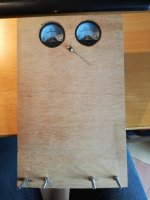
Some remarks about the decisions I made when making this amp:
As can be seen fro the photos, I decided to use 4 meters for the bias setting.
Ralph´s (Atmasphere´s) solution is more elegant, with only one meter pr. channel, but I wanted to be able to monitor the bias of the tubes more closely, as this was the first attempt on such a beast.
As I understand it, with only one meter, if bias in 1 tube changes (DC balance changes), you will have to set all tubes to zero and then adjust 1 set of tubes at a time to restore bias and DC balance.
In my much more complicated scheme, you can monitor each tube for correct bias. There is a switch between the two meters in each channel that switches (via relays) the meters between the two sets of tubes. The bias setting potmeters are beneath the meters and the two to the left are the ones that corresponds to the tube set that is monitored , when the switch is flipped to the left.
The switch at the top center of the front plate is the powerswitch and the switch below is operating relays that shorts the 1 Ohm cathode resistors so the meters are inactive , when playing music. I have always disliked cathode/source/emitter resistors in follower output stages and try to avoid the if possible..
When music is not playing, I can get an idea of how the tube biasing is behaving when deactivating the shorting switch.
If something looks wrong, I use my extra gadget (see the pic.) that goes into the speaker terminals (the four screws that eventually will be replaced by real banana plugs). The switch on the gadget shorts the speaker terminals and now I can set the bias for each tube precisely.
The two meters are for DC balance when the switch are flipped back to non shorting position. And this is used to fine tune DC balance, when cathode resistors are shorted. It is actually not necessary to make this fine tuning, but I wanted to have the opportunity.
Another choice I made was to use multiple small electrolytic capacitors for the power supply instead of a few big. I Like that solution and I had a ton of 3300 Uf /80 V laying around.
By the way, Ralph, we actually met in person in the late '90´s (I think it was 1998 ) while I attended the CES as Technical Director for Bow Technologies in those years.
You probably cannot recall it, but I enjoyed our conversation and you kind personality-
As can be seen fro the photos, I decided to use 4 meters for the bias setting.
Ralph´s (Atmasphere´s) solution is more elegant, with only one meter pr. channel, but I wanted to be able to monitor the bias of the tubes more closely, as this was the first attempt on such a beast.
As I understand it, with only one meter, if bias in 1 tube changes (DC balance changes), you will have to set all tubes to zero and then adjust 1 set of tubes at a time to restore bias and DC balance.
In my much more complicated scheme, you can monitor each tube for correct bias. There is a switch between the two meters in each channel that switches (via relays) the meters between the two sets of tubes. The bias setting potmeters are beneath the meters and the two to the left are the ones that corresponds to the tube set that is monitored , when the switch is flipped to the left.
The switch at the top center of the front plate is the powerswitch and the switch below is operating relays that shorts the 1 Ohm cathode resistors so the meters are inactive , when playing music. I have always disliked cathode/source/emitter resistors in follower output stages and try to avoid the if possible.
. When music is not playing, I can get an idea of how the tube biasing is behaving when deactivating the shorting switch.
If something looks wrong, I use my extra gadget (see the pic.) that goes into the speaker terminals (the four screws that eventually will be replaced by real banana plugs
). The switch on the gadget shorts the speaker terminals and now I can set the bias for each tube precisely.The two meters are for DC balance when the switch are flipped back to non shorting position. And this is used to fine tune DC balance, when cathode resistors are shorted. It is actually not necessary to make this fine tuning, but I wanted to have the opportunity.
Another choice I made was to use multiple small electrolytic capacitors for the power supply instead of a few big. I Like that solution and I had a ton of 3300 Uf /80 V laying around
.By the way, Ralph, we actually met in person in the late '90´s (I think it was 1998 ) while I attended the CES as Technical Director for Bow Technologies in those years.
You probably cannot recall it, but I enjoyed our conversation and you kind personality-
Attachments
Concerning the balanced act:
My current setup is :
Audiolense Speaker and room correction
Foobar 2000
MiniDSP usb streamer.
Ian Canada FIFO -isolator- clock
TDA1543 with my own designed I/U converter.
Arduino controlled lightspeed attenuator.
The Beast.
IDS 25 clones
My balanced act:
Audiolense
Foobar 2000
MiniDSP usb streamer
Ian Canada FIFO - isolator - clock - i2s to pcm with stopped clock option.
4 times TDA1543 where only right channel of the chip is used throughout.
Bruno Putzey's Purist Balanced Preamp
The Beast
IDS 25 clones
Hope this will sing beautifully
In my much more complicated scheme, you can monitor each tube for correct bias. There is a switch between the two meters in each channel that switches (via relays) the meters between the two sets of tubes. The bias setting potmeters are beneath the meters and the two to the left are the ones that corresponds to the tube set that is monitored , when the switch is flipped to the left.
The switch at the top center of the front plate is the powerswitch and the switch below is operating relays that shorts the 1 Ohm cathode resistors so the meters are inactive , when playing music. I have always disliked cathode/source/emitter resistors in follower output stages and try to avoid the if possible.
The cathode resistors play an important role, as they reduce current hogging between power tubes. This is a dynamic issue, so individual bias settings will not solve it. I think you will find that several things happen when they are used: you get more power, lower distortion and greater tube reliability all in one go.
In your case you would also get the possible advantage of an easier metering situation, as the meter could simply monitor the voltage drop across the cathode resistor.
I think your solution of 4 meters is the better way to go but of course its a bit more expensive (if you use a good quality meter) and requires more chassis real estate.
Good work in any event!!
Ok thanks.
My meters are indeed measuring the voltage drop over the 1 ohm cathode resistors.
But anyway, I will try to let the relays just cut the meters from the cathode resistors , when playing music. You cannot have the meters hanging on the resistors when playing music, as they will make strange sounds and behave weird and I have only about 100 Ohms in series with the meters so a lot of power would be dissipated in the meters/resistor.
- Status
- This old topic is closed. If you want to reopen this topic, contact a moderator using the "Report Post" button.
- Home
- Amplifiers
- Tubes / Valves
- 6C33 Circlotron