So, after throwing my two cents in all over this thread where a bunch of ideas were thrown around, I feel that I wanted to start a new thread. I'm not a huge fan of SE, but they are handy when much volume isn't a requirement. Since it's a streamlined, HiFi, chopped-up-champ, I think we can call it the Champion 
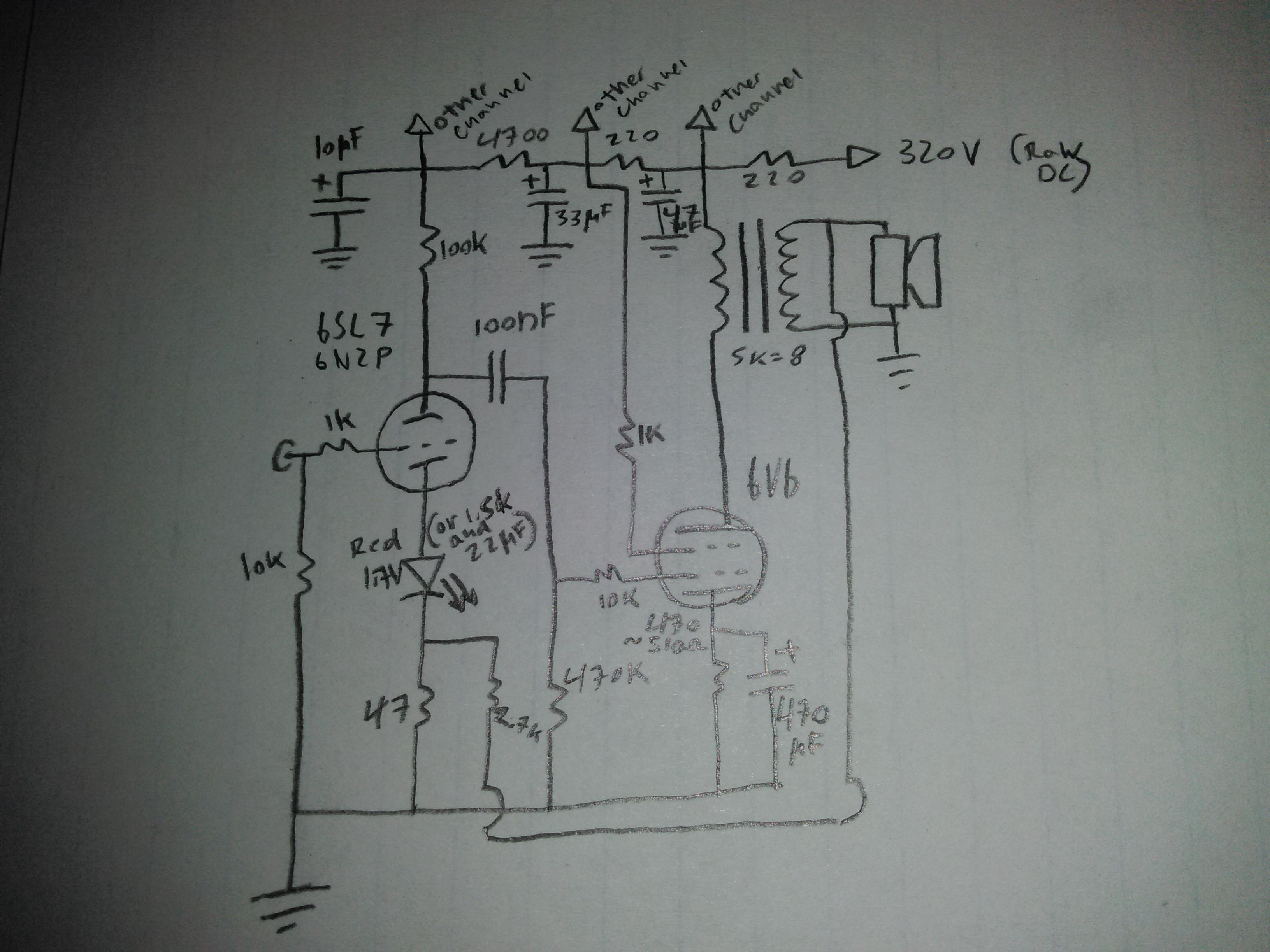
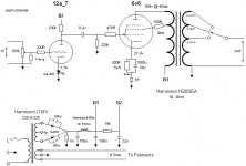
After a few comments regarding the AA764 Fender champ as a quick-n-dirty basis for a Hi-Fi SE amplifier, and similar topologies such as the RH84, I decided to simply post up a hand-drawn schematic of the basic amplifier I've described. I've built a few of these over the years, and have always been happy with them for compact enclosures and low volume requirements. By changing up a few details they will work with most popular tubes, in either position, although the 6SL7 is my favorite, the 12AT7 (with parts changes) would probably be a better choice, and the 6N2P will drop right in, as will the maligned 12AX7 if you must. Don't talk to me about the 12AU7, they suck.
A 6N2P/6P14P version sounds fun...
"there is nothing new under the sun"
Look familiar? It should. 90 percent of SE amps are the same basic thing.
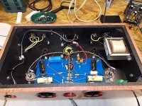
Power supply is as simple as it gets- 240VAC secondary, silicone diodes, and a big fat electrolytic of around 220-470uF, mostly whatever is on hand. Separate filament transformer to suit, preferably center tapped secondary, AC heaters. The filtering happens locally at the circuit as shown on the schematic. Sort of a run-what-ya-got sort of amplifier, just use the basic parts you have on hand. The first couple I built used surplus Valve Junior and Champ transformers form eBay, the nice build used Edcor 10W iron, and a couple others used unidentified console pulls from a repair shop. All sounded great.
Tweaks? Don't get too crazy, remember, MINIMALIST. Less feedback, more feedback, no feedback even (on triode connection) works great. I personally liked it best with a smaller feedback resistor, down to around 680 from the 2700 listed. Definitely sounds best and most clear with feedback, as all SE amplifiers usually do. Swap the LED out for a 1500R/22uF resistor/cap if you must, but I like it with the red LED better. Maybe try different resistor values (within reason) for the 6SL7 anode/cathode to see if you like it hotter or cooler, 150k works well for the anode with a higher (1.9-2.0v) voltage LED. Swap out the output tube cathode resistors as needed, I think 510 works for most 6V6 that I used. I've got a dozen NOS russians that bias up just dandy with that value.
I've even had one apart a dozen or so times to swap out some parts to run some oddball tubes. 35L6, 50L6 and 6K6 in particular are surprisingly nice sounding tubes in a nice circuit such as this.
Switches, knobs, random gauges? NOPE, POWER IS ALL YOU NEED, your source has volume right?
CCS? NOPE
Regulator? NOPE
Stepped attenuator? GET OUTTA HERE
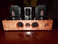
Minimalist, frugal, and boy does it sound GOOD. The Edcor one especially was great, it used a nice pair of 6V6G cokebottle tubes from a dollar bin at an antique store.
Anybody care to comment, chastise, or praise? I feel this is a great baseline to build either a sweep-the-floor type of project, or using boutique parts showpiece. very versatile. I'd love to see more of these little builds, they are nice little rigs when done right.
After a few comments regarding the AA764 Fender champ as a quick-n-dirty basis for a Hi-Fi SE amplifier, and similar topologies such as the RH84, I decided to simply post up a hand-drawn schematic of the basic amplifier I've described. I've built a few of these over the years, and have always been happy with them for compact enclosures and low volume requirements. By changing up a few details they will work with most popular tubes, in either position, although the 6SL7 is my favorite, the 12AT7 (with parts changes) would probably be a better choice, and the 6N2P will drop right in, as will the maligned 12AX7 if you must. Don't talk to me about the 12AU7, they suck.
A 6N2P/6P14P version sounds fun...
"there is nothing new under the sun"
Look familiar? It should. 90 percent of SE amps are the same basic thing.
Power supply is as simple as it gets- 240VAC secondary, silicone diodes, and a big fat electrolytic of around 220-470uF, mostly whatever is on hand. Separate filament transformer to suit, preferably center tapped secondary, AC heaters. The filtering happens locally at the circuit as shown on the schematic. Sort of a run-what-ya-got sort of amplifier, just use the basic parts you have on hand. The first couple I built used surplus Valve Junior and Champ transformers form eBay, the nice build used Edcor 10W iron, and a couple others used unidentified console pulls from a repair shop. All sounded great.
Tweaks? Don't get too crazy, remember, MINIMALIST. Less feedback, more feedback, no feedback even (on triode connection) works great. I personally liked it best with a smaller feedback resistor, down to around 680 from the 2700 listed. Definitely sounds best and most clear with feedback, as all SE amplifiers usually do. Swap the LED out for a 1500R/22uF resistor/cap if you must, but I like it with the red LED better. Maybe try different resistor values (within reason) for the 6SL7 anode/cathode to see if you like it hotter or cooler, 150k works well for the anode with a higher (1.9-2.0v) voltage LED. Swap out the output tube cathode resistors as needed, I think 510 works for most 6V6 that I used. I've got a dozen NOS russians that bias up just dandy with that value.
I've even had one apart a dozen or so times to swap out some parts to run some oddball tubes. 35L6, 50L6 and 6K6 in particular are surprisingly nice sounding tubes in a nice circuit such as this.
Switches, knobs, random gauges? NOPE, POWER IS ALL YOU NEED, your source has volume right?
CCS? NOPE
Regulator? NOPE
Stepped attenuator? GET OUTTA HERE
Minimalist, frugal, and boy does it sound GOOD. The Edcor one especially was great, it used a nice pair of 6V6G cokebottle tubes from a dollar bin at an antique store.
Anybody care to comment, chastise, or praise? I feel this is a great baseline to build either a sweep-the-floor type of project, or using boutique parts showpiece. very versatile. I'd love to see more of these little builds, they are nice little rigs when done right.
Attachments
Last edited:
Help, i shrunk the amp
Mona
neat. saves a few caps, but the bypass at the 6V6 just grew in size physically a good bit. not likely to be an issue though.
why 680k on that upper resistor? surely better to have more voltage across the triode?
That's where I started in the mid 60's. A local ham radio guy gave me a hand drawn schematic of the 5C1 Fender Champ (6SJ7 pentode driving a 6V6, with a 5Y3 rectifier). I would collect parts from junked radios, TV sets, and an occasional HiFi set, found in the local landfill trash dump. I made guitar amps, and a HiFi amp or two. Most of the records that I had were mono, and so was my turntable (a trash rescue out of a HiFi console).
I tried just about every tube that I found in the "amp breadboard" which was 3 tube sockets and a big power transformer screwed to a pine board. Since there were more junk TV sets to pick from, I transitioned to TV tubes early on. The 6BQ6GT horizontal sweep tube has a similar pinout, and will work in that circuit if you connect a plate cap to pin 3. So will the bigger 6DQ6.
I was a young kid who thought he knew everything, but it would be a few years until I understood why the little 6BQ6 was louder and sounded better than the larger 6DQ6. Things like impedance and load lines wouldn't come until technical high school, which still taught tubes in the 60's.
You may find that the 6SL7 is still the better choice. The Tubelab SSE board uses the 12AT7, but that's also the reason for the CCS. The 12AT7 was designed for FM radio tuners, an RF application where extreme linearity is not needed. The CCS will reduce the distortion from the 12AT7 do audiophile levels, and provide enough gain so that a 6550 can be driven to clipping by an iPOD or cell phone.
I discovered the 6SL7 and 6SN7 in the 60's when they were plentiful. The 6SN7's were common in old TV's and was my first choice in a HiFi amp back then because the old "ceramic crystal" phono cartridges of the day put out plenty of signal.
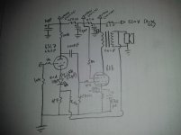
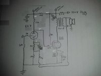
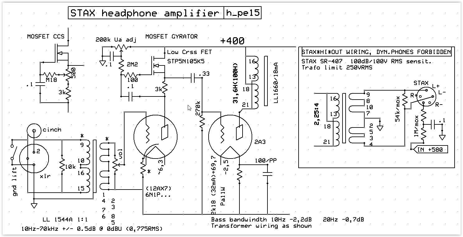
Today there are plenty of 9 pin tubes to choose from in a simple amp. Try a 5751 if you have any. I find them to be a good input tube. It is also possible to build the same amp with a single tube per channel. I have included the schematic of my latest version of the same amp. It can be wired for triode, UL or pentode operation and plate to plate feedback can be used in pentode or UL operation. Parts values depend on the tube choice.
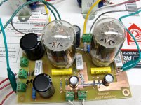
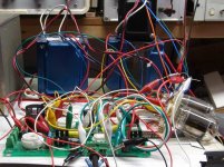
The furball version was my first "modern" version. It was built with a box full of clip leads, an SSE board, and a tube socket board. Surprisingly, it worked well without oscillation, and it was reduced to a simple PC board. I removed the power supply decoupling found in early designs. Modern electrolytics are much better and available in larger values than when the Champ was designed. The amp has only two stages which operate out of phase. Any feedback through the power supply will be negative.
Tube choice:
9 pin 6LR8, 6KY8, 6GF7 All have compatible pinout
12 pin 6LU8, 6MF8, 6JZ8 All have compatible pinout
I tried just about every tube that I found in the "amp breadboard" which was 3 tube sockets and a big power transformer screwed to a pine board. Since there were more junk TV sets to pick from, I transitioned to TV tubes early on. The 6BQ6GT horizontal sweep tube has a similar pinout, and will work in that circuit if you connect a plate cap to pin 3. So will the bigger 6DQ6.
I was a young kid who thought he knew everything, but it would be a few years until I understood why the little 6BQ6 was louder and sounded better than the larger 6DQ6. Things like impedance and load lines wouldn't come until technical high school, which still taught tubes in the 60's.
6SL7 is my favorite, the 12AT7 (with parts changes) would probably be a better choice
You may find that the 6SL7 is still the better choice. The Tubelab SSE board uses the 12AT7, but that's also the reason for the CCS. The 12AT7 was designed for FM radio tuners, an RF application where extreme linearity is not needed. The CCS will reduce the distortion from the 12AT7 do audiophile levels, and provide enough gain so that a 6550 can be driven to clipping by an iPOD or cell phone.
I discovered the 6SL7 and 6SN7 in the 60's when they were plentiful. The 6SN7's were common in old TV's and was my first choice in a HiFi amp back then because the old "ceramic crystal" phono cartridges of the day put out plenty of signal.
Today there are plenty of 9 pin tubes to choose from in a simple amp. Try a 5751 if you have any. I find them to be a good input tube. It is also possible to build the same amp with a single tube per channel. I have included the schematic of my latest version of the same amp. It can be wired for triode, UL or pentode operation and plate to plate feedback can be used in pentode or UL operation. Parts values depend on the tube choice.
The furball version was my first "modern" version. It was built with a box full of clip leads, an SSE board, and a tube socket board. Surprisingly, it worked well without oscillation, and it was reduced to a simple PC board. I removed the power supply decoupling found in early designs. Modern electrolytics are much better and available in larger values than when the Champ was designed. The amp has only two stages which operate out of phase. Any feedback through the power supply will be negative.
Tube choice:
9 pin 6LR8, 6KY8, 6GF7 All have compatible pinout
12 pin 6LU8, 6MF8, 6JZ8 All have compatible pinout
Attachments

Last edited:
More voltage for the triode means higher voltage on the 6V6 cathode = less Vak = less ouput and more loss on the cathode resistor.why 680k on that upper resistor? surely better to have more voltage across the triode?
The Spud-1 is one more variation on the RH84, nothing new

Mona
That's where I started in the mid 60's. A local ham radio guy gave me a hand drawn schematic of the 5C1 Fender Champ (6SJ7 pentode driving a 6V6, with a 5Y3 rectifier). I would collect parts from junked radios, TV sets, and an occasional HiFi set, found in the local landfill trash dump. I made guitar amps, and a HiFi amp or two. Most of the records that I had were mono, and so was my turntable (a trash rescue out of a HiFi console). <snip>
I still need to grab some compactrons and associated sockets to play with, never messed with them yet, but they sure are intriguing.
Yeah, I absolutely love the 6SL7- and prefer using it in most of my projects, it just works so damn well. For something like this they seem perfect. I would like to try some 5751, but don't have any. I have plenty of Russian equivalent 6SN7, 6SL7, and a few each 12AT7, 6DJ8, 6BQ7, 6N2P, and a big pile of NOS 6N1P that sound fantastic. Most of my designs revolve around these simply because I have them, and they are easy to find affordable replacement.
More voltage for the triode means higher voltage on the 6V6 cathode = less Vak = less ouput and more loss on the cathode resistor.
The Spud-1 is one more variation on the RH84, nothing new
Mona
Seems that reduces headroom for the triode though, less available bias for input swing, low voltage across the tube combined with the reduced bias looks to get in the wonky parts of the curves for the 6SL7... Perhaps we have ended up robbing Peter to pay Paul? Might be a good place to try the 6DJ8 though, as these voltages are right where they like it.
We can agree on that.A 6N2P/6P14P version sounds fun... <snip>
But no need to have silicon phobia. It was huge step for me, when i jumped from Ra + bypass Rk --> gyrator+no bypass Rk.
No more muffled sound, microdetail+++, gain goes up ~85x. Impossible thing with any Ra..
2nd thing-Schade on 6v6, make it a low mu triode. then you could remove global fb.
ecc83 has too high ri, and 2a3 miller at treble is high enough to interfere with this driver--when use Ra
Last edited:
Oh believe me, I do not have silicon phobia at all I was just intending for this amp to be a bit more simple. I love playing with CCS loading, and have never really tried Gyrators extensively, but wanted to keep this amp to the basics so to speak. Besides, it's not like the 6V6 requires monster swing, just a nice linear driver with plenty of headroom. I do want to play with gyrators more at some point though...
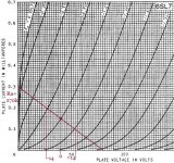
I was just intending for this amp to be a bit more simple. I love playing with CCS loading, and have never really tried Gyrators extensively, but wanted to keep this amp to the basics so to speak. Besides, it's not like the 6V6 requires monster swing, just a nice linear driver with plenty of headroom. I do want to play with gyrators more at some point though...If you look at the curves, it isn't so badSeems that reduces headroom for the triode though, less available bias for input swing, low voltage across the tube combined with the reduced bias looks to get in the wonky parts of the curves for the 6SL7... Perhaps we have ended up robbing Peter to pay Paul?
Mona
Attachments
I'm not so sure that I would be happy running it in this application at those operating points... We only get a volt or so of bias and can only swing 10-12 volts clean with a good bit of distortion. very wasteful way of doing things just to eliminate a coupling capacitor... I'd rather run a 6DJ8 or something similar if going that way, but we have all that B+ available, so I don't mind one more capacitor and resistor if it lets us have a nice clean playground to swing our volts in.
...not bad, but i you put horizontal loadline (gyrator).. it would look betterIf you look at the curves, it isn't so bad
Relatively big value of the resistor powering G2 is the main feature of Fender Champ that causes control of B+ voltage of preamp on overload, i.e. "punch", "sag", and "sustain". Any other amp that uses the same tubes, but with lover value of this resistor, or separate B+ filters for G2 and preamp, is not a Champ.
So, after throwing my two cents in all over this thread where a bunch of ideas were thrown around, I feel that I wanted to start a new thread. I'm not a huge fan of SE, but they are handy when much volume isn't a requirement. Since it's a streamlined, HiFi, chopped-up-champ, I think we can call it the Champion
Hello,
Im thinking if building the amp as I already have a power supply that can provide the voltges needed. I have a few questions.
1. On the 6sl7 cathode, if i use the 1.5k and the cap instead of the red led, do i srill need to keep the 47ohm resistor to ground?
2. I will need to install a pot in front of the 6sl7, can i use 100k instead and replace the 10k resistor with 1 meg to ground. My dac has about 2k output impedance.
3. What are the expected voltages on the 6v6 plate, screen and cathode as well as the 6sl7?
Thank you... I cnt wait to get this started and thanks for sharing.
Best
1. If you go to a resistor on the cathode, you can omit the 47R resistor, and instead attach the feedback resistor to the cathode as well. You will need to change the value from 2.7k to... something else. I would probably start with a 22k~ or so, and see if you like it.
1. That will work fine, and is actually how I do most of my amplifiers inputs usually.
3. These will depend on several factors, but generally the plate of the 6V6 should be a few to a dozen volts under the supply voltage, depending on the transformer and filtering used. The screen will be a little lower than this too. I have to check my notes, but I think the cathode will be around ~22 volts or so? You want maybe 10 watts or so dissipation on the 6V6, so adjust cathode resistor as needed to keep it happy. Maybe start with 470R?
The 6SL7 cathode will be anywhere from 1.4~1.8 volts, with a target of 1.6 or so, and the plate will be around 50~65% of the supply voltage. Adjust the cathode and anode voltage as needed by changing resistor values to suit.
Very versatile, and non-critical. If you are within 10~15% or so on values don't sweat it, as long as you are close it should work well and sound good
Hi Lingwendil,
Thanks for your reply... Ill get started tonight and ill post my results.... I dont have red leds and 47 ohm resistor in ny parts box so i will have to make do with 1.5k// 22uf at this time.
In your first paragraph... you mentioned to change the 2.7k resistor to something like 22k, are you talking about the feedback resistor?
Ill get cracking with amplifier soon.
Thanks again....
Yes, that is for feedback. Don't use feedback if you bypass that cathode resistance, unless you do something similar to the original with the 47R. If you have 100R it will work instead, and maybe try a 4700~5600R for feedback, it's pretty noncritical. I just recommend you run feedback if possible, otherwise output impedance suffers.
If not running feedback, try triode connected on the output. Less power, different sound, but still nice
If not running feedback, try triode connected on the output. Less power, different sound, but still nice
- Status
- This old topic is closed. If you want to reopen this topic, contact a moderator using the "Report Post" button.
- Home
- Amplifiers
- Tubes / Valves
- The Champion SE amplifier, or, chopping up the Fender Champ