Much higher, in the 500volts region.R2 needs to be connected to a higher B++ to fix the voltage.
And the other half doesn't need it, still an assymetric amp and allmost 3W in the driver tube
 .
.Mona
Last edited:
Well, the original GR Experimenter amplifiers used a 550V rated 6S4 for the driver Concertina. It does have to swing output swing + drive swing after all.
The triode Concertina suffers some gm loss via plate N Fdbk. A good high Ri pentode differential driver does not need to suffer that loss (so operating more symmetrically as far as grid gm drives), but does need to cover the voltage swing.
6JV8, at 330V rating, is maybe too wimpy here. Something more like 6GF5 (770 V rating, also available at $1) could be better. 6AH9 maybe (400V), high gm.
Increasing the negative V tail for the driver LTP stage could work instead of higher B++ for R2.
404 Not Found
"If it doesn't work at first, use a bigger tube until it does"
Last edited:
If you like that, go ahead, you still end-up with a miserable amp"If it doesn't work at first, use a bigger tube until it does"

Mona
Up to Rene as to what he wants to do. His Amplifier.
I like the version with just a single primary, since that allows one to use low primary Z OTs, easier self wound ones, or even (cheapskate) power xfmrs for OT (could be series connected even). (one place where bigger output tubes might just solve the problems) I don't worry about 10 Watt drivers if they only cost $1 (ESRC "Dollar Days" list). They even look better. Rene did say "different topology".
Another option:
Put a cascode (Mosfet) above the high swing driver plate to get the HV swing up top. Could put a dummy load resistor between the driver tube plate and the cascode (source) to get both driver plates swinging the same amount for symmetry. About as close to full symmetry as possible now. Can stick with the original 6JV8 driver too.
Attachments
Last edited:
Wow, a bunch of comments, thanks! I was totally off line over the weekend so just now catching up.
Mona, I really want and appreciate your inputs but it would be much more revealing if you were more explicit than simply saying "I don't like it". Why, in detail? I really want to know.
I think some of you talking about leakage inductance and, especially, capacitance, could possibly be missing what may be the single, most important advantage of the Peterson-SInclair (P-S from now on) topology. There is no relative change in voltage between the split primary windings. Ergo, any capacitance, no matter how large, is not being charged and discharged, so there is no current flowing due to capacitive reactance between the windiings. That is a major source of compromise in conventional transformer design which is totally removed from the equation. Less leakage inductance, more capacitance. Less capacitance, more leakage inductance. But here we don't care about capacitance, so all attention can be given to tight coupling between the primary windings with no regard to consequences of capacitance. But even if the windings were done in a, shall we say, more conventional manner, it still would not matter much since there is an opportunity, by means of a suitably sized capacitor, to connect the cathode of Vup to the plate of Vlo and guarantee tight AC coupling.
As to the more complicated transformer by going split rather than single, so stipulated. But the rest of the circuit is much simpler by splitting. And, with a bifilar winding (if heavy insulation is used, #26 has a breakdown value in the many hundreds of volts each, not concerned about insulation issues), the physical winding is little more complex than with a single wire. This is not opinion, it's fact based on years of transformer design and building. At least I'm personally comfortable with this. It's a non issue for me.
Not quite understanding the relevance of the discussion from esteemed member "45". Your points about load impedance ranges, etc, are valid but not part of the discussion of topological merits of the P-S approach. This approach is not inherently better or worse than a standard P-P would be, other than that by using sweep tubes the source impedance is lower and the topology does allow for a lower plate load in the first place, but other means of accommodating changes in load impedance (NFB, etc) are still needed.
Back to the G2 feeding, which is of much importance to many of you and to me, I came up with one of my patented 2AM bolt upright in bed insights. The Vup G2 can be kept well fed throughout the cycle without the use of storage capacitors, and while keeping the current 100% balanced (cancelled) on both primaries, and the Vlo G2 can be fed conventionally from its own regulator (good for both channels). This will be part of the next schematic to be published.
Finally, while a couple of us have clearly wrapped out heads around the P-S concept of the "floating" upper tube, some by your comments, perhaps have not. Please read the P-S article in detail, it's quite complete, make some sketches and convince yourselves that it is, in fact, completely symmetrical with respect to the output load. The drive side does get a bit funky, and one does have to use some imagination to see how the G2s are properly fed while not introducing current imbalance. But it's all totally doable. No additional windings are needed to properly feed G2. None. If I add windings at all, it'll be for a modest amount of CFB. But nothing for the G2s. There is an article available on the internet about an amp called the Horizon. I have attached the link, the article goes through the evolution of the permutations leading up to the single power supply and two primary windings, and even shows the big cap used to guarantee zero AC between the windings. It starts out with the basic P-S concept and ends close to where I want to be.
http://akdatabase.org/AKview/albums/userpics/10004/National%20Horizon%2010%20Article_Horizon%2020.pdf
I suspect a lot of the details being pointed out will come to light in the design refinement process. Items of focus for me are:
-Making sure any G2 current which flows through the primaries are kept strictly balanced
-Making sure the drivers are properly referenced to the respective cathodes
-Making sure the drive levels are strictly balanced (grid to cathode)
-Making sure both tubes are properly biased
-Making sure the transformer design provides good coupling primary to secondary
-Looking at whether a single primary winding is overall simpler than a split approach, all things considered, going all the way back to earlier stages, and the power supply, and the proper care of the heater-cathode voltage limits, and the G2 supply.
-Looking at the Schades. If I even really want them, and if they will be effective. Fortunately, as long as the driver is designed to handle them, those resistors can be added or taken away with not much, if any, complications.
Love the challenges and comments, makes sure I stay honest with the analysis and assessment. When the next schematic is published, it will be accompanied by proper explanations and justifications to make Y'alls analysis more effective.
Happy Fourth!
Rene
Hmm, some disconnection in points being made here I think.
On the Peterson-Sinclair dual primary OT versus single primary. Thinking of the single primary winding OT case, there is capacitance between adjacent turns and between primary to secondary. The dual primary version just splits that primary wire into two adjacent (bifilar) wires with equal AC voltages along it (and different DC V, but irrelevant to the discussion). The two bifilar primary wires are just equivalent to the single wire, except for details.
The turn to turn capacitance is still there, as well as primary to secondary capacitance. However wire surface area is increased with two adjacent wires (higher capacitance) and the winding volume is increased (higher leakage L), UNLESS the primary wire sizes are reduced to half area. Then equivalent resistance stays the same (as long as both wires are handling 1/2 the AC current, which they are with the coupling cap(s) ), surface area is almost back to normal (maybe about 1.4 x greater) and the core volume is about back to the original single wire case. So leakage L is restored.
One can optimise a little further by just incorporating the two wires as separate interleave sets in the design. (so no bifilar)
So net result, the two primary bifilar (or further optimised) design is about the same performance as the single primary design. That's not to say they are the same as the USUAL two primary center tapped design. That design only uses one winding (in class aB) at a time, so the two wires are sized to handle full primary current. Twice the AC voltage is present in the winding volume, so capacitance issues are greatly worse, and leakage L increases from the winding volume increase. Bandwidth is reduced by 1/2.
So the P-S (Peterson Sinclair) designs for OT clearly have advantages over conventional center tapped OTs. The single winding version is much easier to wind, and can be series connected with additional xfmrs (for re-purposed power xfmers as OTs).
The single primary winding OT however requires more complex arrangements for screen grid voltage supplies in the totem pole driver. (Not a big deal now that CCS circuits are readily available however. But apparently it was over-riding back then.)
------
I think Ketje's concerns center on the non-(complete)- symmetry of the totem pole type driver. In theory, the boot-strapped driver can provide identical drive signals to the top and bottom output tubes. In reality, the driver pentodes have finite internal Ri effects, and the greater voltage swing on the one driver plate will introduce some parasitic effects, and wiring capacitance effects around the output tube. The addition of a cascode (with series resistor from driver plate to Mosfet source) above the high V swing driver could remove the Ri effect (matching V swing for both driver pents). Using a heftier (high current) driver can remove any capacitance issues. All this eats up more voltage headroom for the driver, which will need a neg. B supply now. So the halved B+ requirements of any doubled primary winding are gone anyway.
There is also the issue of cathode to heater capacitance of the top output tube. Careful floating heater supply design can minimize that.
The increased requirements around the driver stage have by now probably negated any practical savings around the (P-S) OT (especially considering that all the commercially available OTs are center tapped). But then there really isn't any other option, other than Circlotron, for single winding primary high BW performance (or series connection OTs). Mac comes close in performance, but the OT is complex to wind and still requires the complex driver stage. No series connection option.
So my vote is for the single winding P-S design if you want --outstanding-- OT performance with an easy to wind OT. (trying to wind Mac OTs is just plain stupid!) Attention to detail required in the driver stage for sure, and no real database of existing designs around or experienced designers for this approach. You are in largely unexplored territory.
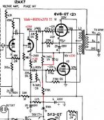
On the other hand, there is a little known trick (used in the Dynaco Mark VI) to extend OT performance (for global N Fdbk purposes). See below. Notice capacitor C7. This transitions the global N Fdbk to local N Fdbk at 60 KHz, the top BW of the OT. This could be arranged at 20 KHz say, for a low cost off the shelf OT. This allows the global N Fdbk to behave throughout the audio BW -AS IF- there were a high BW OT present (no in-band roll-off of the global N Fdbk required). All those super expensive OTs, or alternative high performance designs (like Mac), can be equaled with just a $0.20 capacitor.
So you are now in unexplored territory, to build something exotic, solely for the sake of saying "I did it". Climbed Everest, instead of taking the elevator.
But this is DIY, and we "like" doing that....
On the Peterson-Sinclair dual primary OT versus single primary. Thinking of the single primary winding OT case, there is capacitance between adjacent turns and between primary to secondary. The dual primary version just splits that primary wire into two adjacent (bifilar) wires with equal AC voltages along it (and different DC V, but irrelevant to the discussion). The two bifilar primary wires are just equivalent to the single wire, except for details.
The turn to turn capacitance is still there, as well as primary to secondary capacitance. However wire surface area is increased with two adjacent wires (higher capacitance) and the winding volume is increased (higher leakage L), UNLESS the primary wire sizes are reduced to half area. Then equivalent resistance stays the same (as long as both wires are handling 1/2 the AC current, which they are with the coupling cap(s) ), surface area is almost back to normal (maybe about 1.4 x greater) and the core volume is about back to the original single wire case. So leakage L is restored.
One can optimise a little further by just incorporating the two wires as separate interleave sets in the design. (so no bifilar)
So net result, the two primary bifilar (or further optimised) design is about the same performance as the single primary design. That's not to say they are the same as the USUAL two primary center tapped design. That design only uses one winding (in class aB) at a time, so the two wires are sized to handle full primary current. Twice the AC voltage is present in the winding volume, so capacitance issues are greatly worse, and leakage L increases from the winding volume increase. Bandwidth is reduced by 1/2.
So the P-S (Peterson Sinclair) designs for OT clearly have advantages over conventional center tapped OTs. The single winding version is much easier to wind, and can be series connected with additional xfmrs (for re-purposed power xfmers as OTs).
The single primary winding OT however requires more complex arrangements for screen grid voltage supplies in the totem pole driver. (Not a big deal now that CCS circuits are readily available however. But apparently it was over-riding back then.)
------
I think Ketje's concerns center on the non-(complete)- symmetry of the totem pole type driver. In theory, the boot-strapped driver can provide identical drive signals to the top and bottom output tubes. In reality, the driver pentodes have finite internal Ri effects, and the greater voltage swing on the one driver plate will introduce some parasitic effects, and wiring capacitance effects around the output tube. The addition of a cascode (with series resistor from driver plate to Mosfet source) above the high V swing driver could remove the Ri effect (matching V swing for both driver pents). Using a heftier (high current) driver can remove any capacitance issues. All this eats up more voltage headroom for the driver, which will need a neg. B supply now. So the halved B+ requirements of any doubled primary winding are gone anyway.
There is also the issue of cathode to heater capacitance of the top output tube. Careful floating heater supply design can minimize that.
The increased requirements around the driver stage have by now probably negated any practical savings around the (P-S) OT (especially considering that all the commercially available OTs are center tapped). But then there really isn't any other option, other than Circlotron, for single winding primary high BW performance (or series connection OTs). Mac comes close in performance, but the OT is complex to wind and still requires the complex driver stage. No series connection option.
So my vote is for the single winding P-S design if you want --outstanding-- OT performance with an easy to wind OT. (trying to wind Mac OTs is just plain stupid!) Attention to detail required in the driver stage for sure, and no real database of existing designs around or experienced designers for this approach. You are in largely unexplored territory.
On the other hand, there is a little known trick (used in the Dynaco Mark VI) to extend OT performance (for global N Fdbk purposes). See below. Notice capacitor C7. This transitions the global N Fdbk to local N Fdbk at 60 KHz, the top BW of the OT. This could be arranged at 20 KHz say, for a low cost off the shelf OT. This allows the global N Fdbk to behave throughout the audio BW -AS IF- there were a high BW OT present (no in-band roll-off of the global N Fdbk required). All those super expensive OTs, or alternative high performance designs (like Mac), can be equaled with just a $0.20 capacitor.
So you are now in unexplored territory, to build something exotic, solely for the sake of saying "I did it". Climbed Everest, instead of taking the elevator.
But this is DIY, and we "like" doing that....
Attachments
Last edited:
Could not agree more. The fact remains that intrawinding capacitance, and capacitance between primary and secondary, remains a consideration. But, neither more nor less than for a conventional P-P. The P-S approach makes any lack of perfect magnetic coupling on the primary side a non issue, or allows the bifilar winding of the split primaries without paying the price of interwinding capacitance between the primaries. Again, as stated previously and just now again, the interwinding capacitance between Primary and Secondary consideration remains, and having to drive the intra winding capacitance also remains a consideration, but not any more than with the common P-P.
I think the biggest advantage of the P-S is that, with plate to plate leakage inductance not a factor, class B is fully realizable.
The rest might indeed be climbing Everest just because it's there but, why not? In my professional work, I have to make equipment work at temperatures of 200C and even higher. I like to remind myself when beating my head against the wall while making something work "If it were easy, everyone would be doing it" It's ok if this turns out a bit more difficult in some areas if it makes things better in others.
I do, however, want to do make sure the chosen path is logical. I don't mind the challenges but I do want in the end to wind up with something that will indeed sound good while making the power I would like to have. having it being unconventional is neither a plus nor a minus to me. Again in my profession, more often than not, things are done in an unconventional manner, just to make it work, while other circuits wind up very ho-hum, because it's what works. Just a fact of life.
Detailed analysis will show the way. I just need to make the time! Stay tuned, will have something in the next few days.
Rene
I think the biggest advantage of the P-S is that, with plate to plate leakage inductance not a factor, class B is fully realizable.
The rest might indeed be climbing Everest just because it's there but, why not? In my professional work, I have to make equipment work at temperatures of 200C and even higher. I like to remind myself when beating my head against the wall while making something work "If it were easy, everyone would be doing it"
It's ok if this turns out a bit more difficult in some areas if it makes things better in others.I do, however, want to do make sure the chosen path is logical. I don't mind the challenges but I do want in the end to wind up with something that will indeed sound good while making the power I would like to have. having it being unconventional is neither a plus nor a minus to me. Again in my profession, more often than not, things are done in an unconventional manner, just to make it work, while other circuits wind up very ho-hum, because it's what works. Just a fact of life.
Detailed analysis will show the way. I just need to make the time! Stay tuned, will have something in the next few days.
Rene
Mona, you are right, which is why I'm proposing a +260V supply and limit the swing to 200v, to keep the heater-cathode AC to 200V, in spec for the 6HJ5. To be fair to the Horizon, they do bias the heaters a bit so it's not quite as bad as the portion of the schematic you published, but the tubes are being abused for sure. I promise to pay attention to those kinds of details.
Keep it coming
Rene
Keep it coming
Rene
I don't believe you will ever get a perfect drive regardless of the transformer. So capacitance will matter.I think some of you talking about leakage inductance and, especially, capacitance, could possibly be missing what may be the single, most important advantage of the Peterson-SInclair (P-S from now on) topology. There is no relative change in voltage between the split primary windings. Ergo, any capacitance, no matter how large, is not being charged and discharged, so there is no current flowing due to capacitive reactance between the windiings. That is a major source of compromise in conventional transformer design which is totally removed from the equation. Less leakage inductance, more capacitance. Less capacitance, more leakage inductance. But here we don't care about capacitance, so all attention can be given to tight coupling between the primary windings with no regard to consequences of capacitance. But even if the windings were done in a, shall we say, more conventional manner, it still would not matter much since there is an opportunity, by means of a suitably sized capacitor, to connect the cathode of Vup to the plate of Vlo and guarantee tight AC coupling.
I' d be happy to be proved wrong and will wait and see the results. I have several nice sweep tubes and until now I have only done one "modified ultralinear" class A (into nominal 8ohm) amp that can drive down to 2 ohm without changing secondary tap.....that's what I meant regarding power delivery.
Last edited:
Thanks, 45.
Yes, of course, no perfect components, totally agree. But the point is, if one starts with something which fundamentally does not care about leakage inductance, for example, then an imperfect component with leakage inductance will matter less. If one has a circuit which fundamentally, even if only in theory, produces no net AC between two given points, then even in the presence of imperfections it could be better than a circuit where capacitance is a theoretical and practical factor. The P-S topology fundamentally does away with two of the many concerns one has when designing transformers and output stages, even while introducing unusual complexity.
The potential advantages are important and they are the reason I want to fully investigate this and not dismiss it out of hand.
Your comments about handling a load are, of course, correct. I don't believe the P-S output stage to be any more or less capable than any other traditional stage. There is no reason why it could not be operated in Class A, for example, you just won't get nearly the power than if operated Class B, or even AB. The use of sweep tubes allows a fundamentally lower ZOut because the turns ratio need not be as aggressive as with High Z tubes, and feedback will lower the effective Z out anyway.
So, I am in agreement that there are no perfect parts, but there are circuits which can be more tolerant than others. And the lower the Z out the better as it then becomes a constant voltage source and can drive any impedance, though maximum power transfer still occurs when source and load are matched.
And my hat is off to you for having built something that can drive down to 2 Ohms with no tap matching. What tubes were used? What power at best load impedance? Or at a common 6-8 Ohms? Have you measured it in terms of distortion? How does it sound?
Rene
My concern is not about the output transformer but for the rest of the circuit. In this respect I think Mona is not wrong about asymmetry. Although I have not done much thinking about class B operation, because I do not use it, your analysis about leakage inductance and capacitive currents is ok to me but with this circuit you are basically transferring the "capacitive issue" elsewhere in the amp. This is also mentioned in the article but apart from same practical suggestions on how to tune the circuit there is no quantitative discussion. Likely this is due to the fact that parasitic capacintances always unknown in practice and also depend on the actual construction of the amp so that two amps that use the same circuit but made by two different persons in two different ways might not behave the same way.
This aspect looks a bit tricky too me but I might be wrong and in the end tuning the amp is not a big deal.
The tubes I used were the 6DQ5s as I inherited these from my daddy who uses them in his radioamateur gear. That was a while ago. Recently I have bought some other sweep tubes at for 3-4$ each. Almost all with no anode cap: 6GE, 6JA5, 6HB5 and 6HJ5....I do not like anode caps. The only type with anode cap is the 6HF5. But only have a few of this type.
The amp could drive the 2 ohm delivering more power than 8 ohm however max Pout was achieved into 4 ohm. There are other amps that can do this including the classic McIntosh but amount of output power into lower load respect to nominal is worse. Still it can do it....I am citing the Mac becuase of its original intent to use class B.
For my amp distortion was higher respect to 8 and 4 ohm but very accepetable and within 2-3% as the amp used local fb only. For the Mc that also uses loop fb is less...within 1% I think.
You can do an amp that can drive 4 ohm speaker from the 8 ohm tap also using simple pentode connection and loop feedback. THere is one that was posted a few days ago by user Walge using 4xKT150 per channel. The "secret" is to bias the tubes in class A or high current class AB. In that case continuous power into 4 and 8 is the same (max is for about 5 ohms) but impulsive power into 4 ohm is much better. See the pdf attached here: http://www.diyaudio.com/forums/tubes-valves/309166-fab-four-4-x-kt150-monoblock.html
You can also see that in this case the amp can still deliver about 40-50W into 2 ohm.
Last edited:
The 6DQ5 is an older but close cousin to the 6HD5 and 6HJ5. It is an aesthetic thing mostly in audio, I happen to think plate caps are cool.
An earlier suggestion is the 6GF5, but it seems like a much less capable tube in terms of current, with a peak Ik rating of 500 mA to the others at 1000mA.
I'm going to spend time digesting all the comments about shifting burdens of driving capacitances from the output stages to earlier ones, this is not immediately obvious to me and it seems, again at first glance, that there is neither relief nor burdening caused by this topology relative to others and the same concerns and techniques exist for the P-S as for any other. Intuition, not analysis, we'll find out later.
And I will continue to look at the claims of asymmetry, on the driver side. Right now, I don't see them. My vision of the driver stage has been a differential driver with a very long tail (so it will not be starved when the plate of Vup swings toward ground), connected as shown in the crude diagram posted a while back. Asymmetry of configuration, yes, so is a "concertina", but dynamic asymmetry, no. Again, at least not so far. I'll get into the details during the rigorous analysis. Right now, I will again admit that it's all intuitive.
I like the idea of MOSFET source follower drivers because they A) allow the elimination of caps on the G1 circuit of the outputs (blocking distortion potential) and, B), reduce the burden on the drivers which allows easier and larger voltage swings at their plates.
But whether my intuition agrees with y'alls comments right now, or not, each and every item being mentioned is going on my list of things to analyze so, please, keep it coming, especially when a rationale is provided.
Back to the salt mine!
Thanks,
Rene
This is what it says:
"For best operation at high audio frequencies, it is important to keep stray circuit capacitances as small as possible. Particular attention should be paid to the capacitance to ground of the circuit from the plate of the driver stage to the grid of the upper output tube. This capacitance, which shunts the phase inverter plate-load impedance, is effectively multiplied by the gain of the output stage. For the present circuit this factor is about ten."
Now this solution with bootstrapped concertina is pretty common in OTL amps which are basically identical except the use of the output transformer (and of course a re-worked power supply to have DC coupling). I can't be sure because I never used it. I also think I might be wrong if I take into account the other claim that class AB amps have high frequency distortion because of the switching transients. This is not true in general. It's only a problem with class B amps (that are usually not considered for Hifi) or when using poor transformers. People only care about frequency response but in reality for an output transformer having flat frequency response well beyond the audio band the primary impedance will drop a bit earlier or a lot earlier depending on how it's been made. In other words for some it's much worse than others or for some it is not a problem and for others is. It depends on the design. Generic, cheap transformers are usually those causing troubles....
Last edited:
Very interesting comment regarding the drive. It's on the list. On the plus side, the G1 to other electrodes capacitance is not great. 0.5pF G1-plate, low effective mU so not much effect there, and a total of about 25pF G1 to K, G2 and G3 combined. Not negligible but not enormous either. Your caveat about strays is probably more important here than the interelectrode caps.
I don't intend to use a "cheap" (to me, meaning compromised for the sake of driving the cost down as the primary goal) transformer. It will be what it needs to be, using good engineering practice.
Class B is to get the 60W at the now lower supply voltage, but I can always change bias and give up maximum power if it turns out to be necessary. Class B is avoided in the Hi Fi world because of "notch" distortion caused by leakage inductance in the primary circuit, and perhaps due to general opinions by the "gurus" out there. The P-S approach fundamentally eliminates this effect, as the Mac approach did using a different method. Some of those ran Class B. If in the end, what I build sounds good to me in Class B, or if it has to be throttled back because it needs to run in Class AB, I think I'll be OK with it. We will all have learned something.
Thanks
Rene
The 6GF5 tube was mentioned for a HV driver, not an output tube.
The totem pole differential driver stage has to handle at least 2x B+ for swing to the top output tube grid plus parasitic capacitances (so a current requirement too).
6GF5 is rated for 770V. It is basically a trimmed down (smaller plate) version of the 6GE5. (can use the 6GE5 curves for it) The 6JN6/6GE5 has gotten very good audio results in Pete's DCPP amplifier as an output tube. Tektronix used 6GF5 in some of their tube scopes, it may even have been custom made for them. It can drive most any power grid with real authority (500 mA peak!).
(H-K Citation II is one rare example of an amplifier with an authoritative driver stage, 12BY7, 75 mA peak)
Last edited:
That makes a great deal of sense. Or stick with the 6JV8 and add MOSFETs. But whichever way, being able to source enough current is of course a must. One attractive thing about the 6JV8 is the triode section, really nice and the tube's price is very low. I can afford to buy a ton of them for future spares. But I have to say that I was considering several of the frame grid types for the drivers and still open to whatever type will handle the driver function best.
Am aware of the need for the driver to swing a lot. The upper voltage end is handled by the connection of the lower driver's plate resistor to the plate of the lower output, going low I'm anticipating handling by returning the cathodes of the drivers to about -150. In theory, linearity of the drivers once the PA G1 drive is below cutoff is not important, as long as the level does remain below cutoff for the appropriate portion of the cycle. The 6JV8 can swing 30mA. If not enough after analysis then it shall either be changed, or helped with MOSFETs.
The numbers I'm throwing about are strictly spit wad, no real calculations yet so math will tell the tale.
Thanks!
Rene
6GE5 is nice in triode mode as well.The 6JN6/6GE5 has gotten very good audio results in Pete's DCPP amplifier as an output tube.
The one I expect most from is the 6JA5 that, at least from datasheet (look for 10JA5, 10.5V volts variant), is quite linear with Vg2=125V. Don't rembember any other pentode like that.
- Status
- This old topic is closed. If you want to reopen this topic, contact a moderator using the "Report Post" button.
- Home
- Amplifiers
- Tubes / Valves
- 60W With Sweep Tubes, Different Topology