I have check some tubes.
Look at attach
I have made a siple circuit with a 28 H chocke, 300 vdc and some bias current.
The 28 H at 2 kHz has a very high impedance so I can look at the Rp related to the current
In this case we reach the best results ( on lab but also on listening test) with lower Rp , of course
Walter
Look at attach
I have made a siple circuit with a 28 H chocke, 300 vdc and some bias current.
The 28 H at 2 kHz has a very high impedance so I can look at the Rp related to the current
In this case we reach the best results ( on lab but also on listening test) with lower Rp , of course
Walter
Attachments
Perhaps I did not understand the translation. But any tetrod and pentode have an optimal load R, when the distortions of the 3rd and 2nd harmonics are minimal, and the power is maximal. Thus, for different lamps, the ideal load resistance R will be its specific for a given tetrode (pentode). I'm sure you know about this, the problem is probably related to translation difficulties or skipping small details in the description of the test that I do not see.
http://paseka24.ru/sites/default/files/6p18p_0002.jpg
http://electroshema.com/data/tom8/151%20-%200577_files/151%20-%200577-2.jpg
http://paseka24.ru/sites/default/files/6p18p_0002.jpg
http://electroshema.com/data/tom8/151%20-%200577_files/151%20-%200577-2.jpg
Last edited:
I know the relation between the Rp and optimal load.
But I have to test with a reasonable Load which one of the tubes liste has the best performances when we change the load, quite similar to the real loudspeaker.
With El34 the results are good also the sound, but with KT120 you get more capability to drive heavy loudspeaker.
The FReq/Thd diagram show you what happen on different setting.
It was a very interesting job, for me.
Walter
You have access to an excellent test base and probably the opportunity to publish material in the magazine. I think if you typed such dependencies as in attached files in my message and for popular tubes (6L6, EL34, KT88, KT120, KT150, EL156, EL509), your article was read and quoted around the world and for a very long time.
to ssr2
It is dangerous to do this!!!")
But if you look on diagram I sent about the test with different loads you can see that with EL34 there are limitation on delivery current when the load become low.
With KT120 the situation is much better.
With this thest we can understand with a reasonable precision what the amp can do with a complex .
This amp has a open loop BW of about 60 KHz and the feedback is very low, the out put impedance is also reasonable low
Walter
It is dangerous to do this!!!
But if you look on diagram I sent about the test with different loads you can see that with EL34 there are limitation on delivery current when the load become low.
With KT120 the situation is much better.
With this thest we can understand with a reasonable precision what the amp can do with a complex .
This amp has a open loop BW of about 60 KHz and the feedback is very low, the out put impedance is also reasonable low
Walter
Again,
if you look on the test I mentioned you can see how current the amp can delivery respect to the load
Fig. 6 on post 1 is with EL34
Fig. 9 with KT120
if you look on the shape of the curve you can see the differences respect to the load.
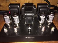
Now the amp with KT120 is driving with a great satisfaction ( of my friend) a pair of B&W 800 in a medium size room.
I can send the photo of installation, if you don't believe.
Walter
if you look on the test I mentioned you can see how current the amp can delivery respect to the load
Fig. 6 on post 1 is with EL34
Fig. 9 with KT120
if you look on the shape of the curve you can see the differences respect to the load.
Now the amp with KT120 is driving with a great satisfaction ( of my friend) a pair of B&W 800 in a medium size room.
I can send the photo of installation, if you don't believe.
Walter
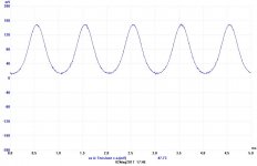
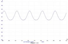
I forgot to send two diagram to shoe the class A operation of this amp with KT120.
This tube can allow to run with a high current
The signal was taken from a 1 ohm resistor that I use as bias monitor for each tube
in fig. 10 there is a signal with 50 mA , about 10 watt at the output on 8 ohm
in fig. 11 with 90 mA, about 30 watt at 8 ohm, in this case each 120 is dissipating around 41 watt; on post 1 fig. 6 is possible to see the difference on THD vs Freq with this bias current
Walter
Attachments
Last edited:
Thus, for different lamps, the ideal load resistance R will be its specific for a given tetrode (pentode).
For any pentode( either 3-grid, or beam tube ), the ideal load resistance depends on the operating point set with the g2 voltage. For something like an EL34, the g2 voltage on a 5k a-a load will be radically different from a 6Pi41S at the same plate voltage and idle current.
The g1=0V envelope set by the g2 voltage, is how the combination of a-a load and B+ are chosen. While I see the benefit to playing with AB1 for horsepower racing, the amps sound better when set up for Class A operation.
cheers,
Douglas
About the choice of tetrode mode everything is accurate. But 6P41S and its screen grid are included even in the UL scheme without problems, from its high power and frame design, which also reduces the current of this grid. C EL34 it was not compared because the EL34, more high-voltage and powerful. 6P41C was compared to a similar in power and voltage EL84.
Ciao Walter,
so based on your table here: P-P with EL34/KT120 we can get better Zout at a lower price with an hextet of EH6AC7 rather than a pair of KT150. And based on what can be read online, reliability would be much better.
so based on your table here: P-P with EL34/KT120 we can get better Zout at a lower price with an hextet of EH6AC7 rather than a pair of KT150. And based on what can be read online, reliability would be much better.
- Status
- This old topic is closed. If you want to reopen this topic, contact a moderator using the "Report Post" button.
- Home
- Amplifiers
- Tubes / Valves
- P-P with EL34/KT120