Hi Ian,
Thanks for the help, but if you look to post 37, you will see that the jumpers are not mirrored
I have done that to avoid error and on both channel jumpers should be on the same side and position 1-2 for the PC900 and 2-3 for the PC97... I checked on the PCB and pin 1 of the jumper goes to pin 1 of the tube !
We have to find an other cause for this problem unfortunately.
Marc
I am hesitant to remove the MOSFET because de-soldering and re-soldering plated holes is a mess
I checked the PCB and the resistors and everything is OK ! I will try to make some measure with a low plate voltage, like 50 V instead of 300 V to check the circuit without the risk to kill the transistor...
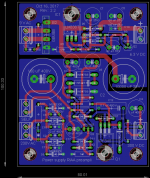
Thanks for the nice remark about the PCB, I like to design them and I try to improve my capability by learning from the mistake I made in the past
Marc
I checked the PCB and the resistors and everything is OK ! I will try to make some measure with a low plate voltage, like 50 V instead of 300 V to check the circuit without the risk to kill the transistor...
Thanks for the nice remark about the PCB, I like to design them and I try to improve my capability by learning from the mistake I made in the past
Marc
Installing pins or solder lugs in the plated-through holes, then solder theI am hesitant to remove the MOSFET because de-soldering and re-soldering plated holes is a mess
I checked the PCB and the resistors and everything is OK ! I will try to make some measure with a low plate voltage, like 50 V instead of 300 V to check the circuit without the risk to kill the transistor...
Thanks for the nice remark about the PCB, I like to design them and I try to improve my capability by learning from the mistake I made in the past
Marc
mosfet on the lugs. Easy to remove, easy to replace.
One might even solder wire-wrap pins in the holes and mount
"berg-connectors" on the mostfet, this will mount a mosfet without
even soldering at all.
That is a good point to put "socket" for the MOSFET, it is so easy with tubes
In the mean time I have made several tests with high voltage up to 120 V to keep the MOSFET under excessive power dissipation and I have found two things:
1) The resistor R29 of 27k was not correctly soldered and the plate of the 12AU7 was not powered... The reason is quite stupid, the holes for the 1W resistor were too small at 0.8 mm and I had to drill them, of course this has broken the platted through hole and when I soldered the resistor I have forgotten one pin on the top
2) I was also surprise that it was this channel that didn't work, in fact when I followed the signal, I have found that I made at least one mistake on the PCB design, I have switched the two channels on the output connector !!! Left is on the right connector (pin 5 & 6 of X1B should be reversed). This is not very critical when you know it and if you connect RCA plug with wire you can just connect the opposite pin, with the PCB connector you should remember to connect left on red and right on white (the opposite of the input)...
After this I found that one channel was still very weak, and I have discovered that the cold MOSFET was in fact nearly dead
I need a more powerful device, I don't understand why because even with 300 V the current is not so high and there is no oscillation ?
I will continue to check...
Best regards,
Marc
Hi,
I have made a lot of progress on the test of this RIAA amplifier
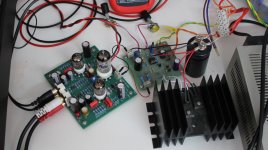
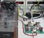
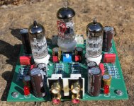
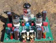
I replaced the dead MOSFET with a STU9HN65M2, it's a brand new MOSFET from STmicro with Vds of 650 V, Id of 5.5 A, Rds of 0.82 ohm and Crss of only 0.85 pF ! It is available in IPAK package (like a DPAK with lead) I have soldered it on the lead of the dead TO92. For the test, I also replaced the old low end Thorens TD280 MK IV turn table with a much better Thorens TD160 and a Shure M95ED cartridge (third photo) ! What a huge difference, now I really like the result
I have used a variable power supply for the test (first photo) and at the beginning I was using only 150 V DC to limit the power dissipation in the MOSFET but later I have increased the voltage to 250 V, still not the specified 300 V but the MOSFET temperature is already 60°C on the STQ3N45K3-AP and... 80°C on the tab of the STU9HN65M2
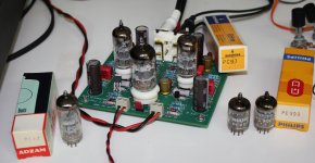
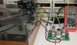
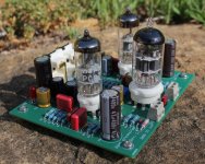
Anyway, I have listened many LP all the day while I was working on other things (including the new EL34 / 6CA7 Baby Huey) and I was very happy with the result I have also tested PC97 version, and we should not forget to change the red jumpers because it will make a big moise in the speakers, guess why I know that ? You can see on the second photo different tubes and the 252 V on the voltmeter on the last photo.
This RIAA amplifier is now playing very good and the only problem was the power dissipation of the MOSFET (and my bad old turn table which gave me a lot of noise...). I will continue to try to improve it with other TO220 MOSFET that I have received in the mean time...
Cheers,
Marc
I have made a lot of progress on the test of this RIAA amplifier
I replaced the dead MOSFET with a STU9HN65M2, it's a brand new MOSFET from STmicro with Vds of 650 V, Id of 5.5 A, Rds of 0.82 ohm and Crss of only 0.85 pF ! It is available in IPAK package (like a DPAK with lead) I have soldered it on the lead of the dead TO92. For the test, I also replaced the old low end Thorens TD280 MK IV turn table with a much better Thorens TD160 and a Shure M95ED cartridge (third photo) ! What a huge difference, now I really like the result
I have used a variable power supply for the test (first photo) and at the beginning I was using only 150 V DC to limit the power dissipation in the MOSFET but later I have increased the voltage to 250 V, still not the specified 300 V but the MOSFET temperature is already 60°C on the STQ3N45K3-AP and... 80°C on the tab of the STU9HN65M2
Anyway, I have listened many LP all the day while I was working on other things (including the new EL34 / 6CA7 Baby Huey) and I was very happy with the result
I have also tested PC97 version, and we should not forget to change the red jumpers because it will make a big moise in the speakers, guess why I know that ? You can see on the second photo different tubes and the 252 V on the voltmeter on the last photo.This RIAA amplifier is now playing very good and the only problem was the power dissipation of the MOSFET (and my bad old turn table which gave me a lot of noise...). I will continue to try to improve it with other TO220 MOSFET that I have received in the mean time...
Cheers,
Marc
Attachments
Thank you Merlin, it is the result of your nice schema with your suggestion for the MOSFET output, I only made the PCB and I like to design them, not only for the functionality, but also for an aesthetic symmetric look and as compact as possible
Now I run the RIAA preamp at 275 V, I even made a test at 300 V but the STU9HN65M2 tab was at 102°C and I didn't want to do that too long
The preamp is doing very well, with the Thorens TD160 and a Shure M95ED cartridge I have played some old "Clear Crystal Record" Direct to Disk Recording and the sound is excellent :
Tchaikovsky - Cincinnati Symphony Orchestra, Erich Kunzel – 1812
Virgil Fox – The Fox Touch Volume Two
San Francisco Ltd. – San Francisco Ltd.
I have tested two PC97 ( Siemens and ADZAM) and one PC900 (Philips) and I didn't found a significant difference between them Both sound very good
As you can see on the Siemens and on the Philips photos, the two red jumpers are in different locations to accommodate the different pinout of the tubes... Now I still need to test a bigger TO220 MOSFET to have a lower junction temperature and I also have to design the power supply PCB. Finally I need to find a nice enclosure to put everything in a box.
Cheers,
Marc
Now I run the RIAA preamp at 275 V, I even made a test at 300 V but the STU9HN65M2 tab was at 102°C and I didn't want to do that too long
The preamp is doing very well, with the Thorens TD160 and a Shure M95ED cartridge I have played some old "Clear Crystal Record" Direct to Disk Recording and the sound is excellent :
Tchaikovsky - Cincinnati Symphony Orchestra, Erich Kunzel – 1812
Virgil Fox – The Fox Touch Volume Two
San Francisco Ltd. – San Francisco Ltd.
I have tested two PC97 ( Siemens and ADZAM) and one PC900 (Philips) and I didn't found a significant difference between them
Both sound very good As you can see on the Siemens and on the Philips photos, the two red jumpers are in different locations to accommodate the different pinout of the tubes... Now I still need to test a bigger TO220 MOSFET to have a lower junction temperature and I also have to design the power supply PCB. Finally I need to find a nice enclosure to put everything in a box.
Cheers,
Marc
Attachments
can you heat sink the STU9HN65M2 ? I always heat sink source followers, (if possible).
It should be possible to heat sink STU9HN65M2. even a small heat sink will help. I have some small ones that fit T-220 that help bring down the temperature a bit. Maybe this won't work on your pcb though....
Alternatively, you could simply run less current through the STU9HN65M2.... increase R14/R33 in your schematic.
Strange that your mostfet died.. you have a diode to protect the gate - maybe check it to see if it is not defective (!)
Ian
Last edited:
i use it on ecc83 (very high ri, no prob) gyrator, sound is sharp as razor
Went thru all mfg., only ST has so low Cgd fets..
oh, another.. STF3LN80K5 - N-channel 800 V, 2.75 Ohm typ., 2 A MDmesh K5 Power MOSFET in a TO-220FP package - STMicroelectronics
holy crap. this is one I want to try...

Hello,
Even if I have been very busy with the Group Buy for the Baby Huey EL34 amplifier, I have found the time to design a power supply PCB for the RIAA tubes preamp. This small module will give a 6.3 V DC regulated output for the tubes heaters and a 300 V DC high voltage stabilized for the tubes plates. I am waiting for some PCB soon and I will post photos and comments when this small power supply will be tested.
Best regards,
Marc
Attachments
- Home
- Amplifiers
- Tubes / Valves
- Merlin RIAA Preamp