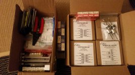
As the title says, i'm working on building the Engineer's Amp. I'll post my progress here, I suppose with plenty of pics. I got all the parts in and the tools I needed for the through-hole components, to bend the leads of course.
Anyone who's successfully built this amp, please feel free to suband tag along. I'm sure I'll need good advice along the way. This is my first tube amp and I'm super stoked!
Anyone who's successfully built this amp, please feel free to suband tag along. I'm sure I'll need good advice along the way. This is my first tube amp and I'm super stoked!
Attachments
Last edited by a moderator:
Anyone who's successfully built this amp, please feel free to suband tag along.
Ok.
")
jeff
Still in box, I bought a new digital Weller. My old chicom two in one was having trouble keeping the tip temp consistent, specially with the larger tip. It gave me four good years though. I may have left it on all night once or twice...
Speaking of soldering. Does anyone think it would be worth using silver solver? I have a tube of silver solder I purchased a while back and never found a use for it but I read that it works well in audio? I can't imagine the difference would be audible but any reason why I should skip the silver solder and instead use traditional lead/rosin core solder? I also plan to use liquid flux.
Speaking of soldering. Does anyone think it would be worth using silver solver? I have a tube of silver solder I purchased a while back and never found a use for it but I read that it works well in audio? I can't imagine the difference would be audible but any reason why I should skip the silver solder and instead use traditional lead/rosin core solder? I also plan to use liquid flux.
Boy, no one ever told me that having a kid would take up all my time... My parents are coming to visit this weekend. Assuming the Cardas solder arrives by then, I will begin soldering this Saturday. Or.... Ill go biking..
On another note, maybe you guys can help me with something else? Follow the link to another thread I created to help identify an older transformer. Maybe I can use it for a project down the road?
http://www.diyaudio.com/forums/parts/307458-help-identify-transformer.html#post5071899
On another note, maybe you guys can help me with something else? Follow the link to another thread I created to help identify an older transformer. Maybe I can use it for a project down the road?
http://www.diyaudio.com/forums/parts/307458-help-identify-transformer.html#post5071899
Last edited:

Agreed, and use some good flux too. I have pretty much always used leaded multicore solder alongside a good paste flux. I have worked a bit with one of those flux pens on pcb's, sort of looks like a paint pen, seems to work OK. I still prefer paste myself, either dipping wire ends/components or using a small applicator like a small acid brush for pcb work.
Good luck on the build!

I found a place that sold little bottles with brushes once, just like a nail-polish bottle. I don't remember where now. This has become my favorite way to apply flux. Very easy to control how much you are applying and put it exactly where it is needed, and it is all self-contained. Lid keeps it fresh and you never have to clean the brush.
I have something like that for alcohol, works very well.
Another questions you guys might be able to help me with. I don't want the components sitting directly on the pcb, I don't like the look, I don't think it looks professional. I want to space the components such as resistors off the board by at least a 1/16th. I've seen some places online sell spacers that go on the legs and dissolve away with an alcohol bath. I've also seen components legs get a bend that prevents them from going in too far. I don't like the second option because it requires a very expensive pair of pliers and it can introduce interference if the leads are too long. Anyone have any other ideas or solutions?
http://s3.amazonaws.com/MagicHour/USTech/Uploads/Multiseals.jpg
Also, anyone care to chime in if I should be using some sort of adhesive for the capacitors? If so, what should I use?
Last edited:
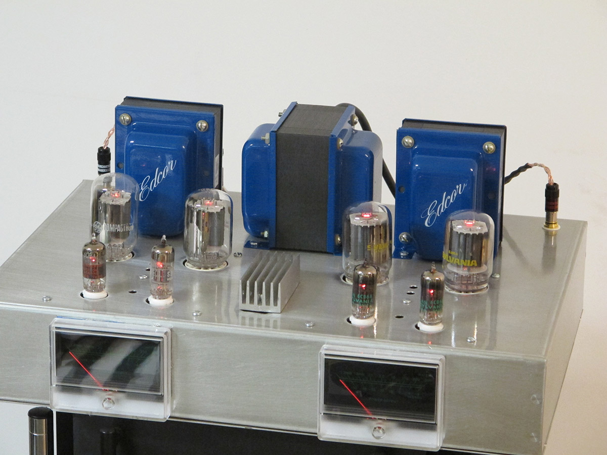
Note that the Edcor Transformers (which I use) are wired a bit differently from the Hammond which Pete currently has specified on his website schematic.
I found that I could optimize the results by swapping around the tubes until best match was attained. I did this with a distortion analyzer -- you don't need an expensive distortion analyzer for this amplifier.
It's sound is quite pleasant sounding.
I found that I could optimize the results by swapping around the tubes until best match was attained. I did this with a distortion analyzer -- you don't need an expensive distortion analyzer for this amplifier.
It's sound is quite pleasant sounding.
I wasn't aware that a Hammond transformer was specified, I was under the impression that he spec'd out Edcor. Edcor even carries a line of transformers for Pete specifically for this project, you can buy the trio in one swoop. I'll have to check I suppose but it is what it is, I already have the transformers in hand.
I have something like that for alcohol, works very well.
Another questions you guys might be able to help me with. I don't want the components sitting directly on the pcb, I don't like the look, I don't think it looks professional. I want to space the components such as resistors off the board by at least a 1/16th. I've seen some places online sell spacers that go on the legs and dissolve away with an alcohol bath. I've also seen components legs get a bend that prevents them from going in too far. I don't like the second option because it requires a very expensive pair of pliers and it can introduce interference if the leads are too long. Anyone have any other ideas or solutions?
http://s3.amazonaws.com/MagicHour/USTech/Uploads/Multiseals.jpg
Also, anyone care to chime in if I should be using some sort of adhesive for the capacitors? If so, what should I use?
I've used resistor lead-bending jigs like this one: http://www.mouser.com/ProductDetail/SparkFun-Electronics/TOL-13114/?qs=WyAARYrbSnacy5bPO92d8g%3D%3D&gclid=CjwKEAjwr_rIBRDJzq-Z-LC_2HgSJADoL57H8e4_xQO2uCrKivzhRRPo8H_slZRoVna78u6nnJVf8xoCVX3w_wcB
When I want some clearance, I simply insert the resistor into the holes as far as I want it and give a little outward bend to the leads on the solder side. Then I solder it in. This is easiest done with the board held in a vise so that gravity will hold the resistor in the proper position.
Yes, I did end up buying a lead forming jig, I got this one from Germany since its well designed to hold multiple sizes of diodes with same hole spacing. You can use the really small diodes or the really fat ones;
Bending Device Resistors LED Diodes Components Bending CONDENSOR
I like the idea of bending the leads after inserting and letting gravity pull the diode down, I may resort to that.
Bending Device Resistors LED Diodes Components Bending CONDENSOR
I like the idea of bending the leads after inserting and letting gravity pull the diode down, I may resort to that.
I wasn't aware that a Hammond transformer was specified, I was under the impression that he spec'd out Edcor. Edcor even carries a line of transformers for Pete specifically for this project, you can buy the trio in one swoop. I'll have to check I suppose but it is what it is, I already have the transformers in hand.
I have two versions of the schematic --- on the current one (5/19/17) it has the Edcor's.
The 50W version specifies the Hammond. I will get around to building that one some time this fall.
http://www.diyaudio.com/forums/atta...ed-new-p-p-power-amp-design-dcpp_finished.jpg
Last edited:
I got my solder this weekend but then realized that I was out of Kester flux. Oy vey...
While that's shipping, what do you guys think about components like capacitors, specially the larger ones? I see that some OEM's use some goo-shmoo to keep the components from vibrating. Can you guys suggest something?
The PCB is of good quality even though it does have a slight twist to it, not sure why. I do want this PCB to be built to the highest spec possible, I don't like doing things half-assed..
I'm still thinking about spacing components off the board. Trying to inject some logic into both arguments of leaving the components against the board or spacing then, even if its only 1/16th or 1/32nd. I just hate the idea of heat dissipating into the PCB from resistors, specially that larger ones. I don't plan to leave the leads long enough to introduce rf cross communication, I think im safe from that.
I'm still thinking about spacing components off the board.
Good idea for the larger wattage-value resistors. Will prevent scorching of the PCB.
Suggestion -- before you stuff the board, use it as a template for cutting the chassis drill holes/socket holes/transformer feed through's etc. Pete provides a DXF file, but it is easier to just lay it down on the chassis and use a pencil to mark out the holes.
It is indeed a well designed PCB.
- Status
- This old topic is closed. If you want to reopen this topic, contact a moderator using the "Report Post" button.
- Home
- Amplifiers
- Tubes / Valves
- Build Log: P Millett's DCPP "Engineer's Amp"