This is a grounded cathode amplifier. By the looks of it it will give a signal gain of 10-14.
A buffer is made from a cathode follower 99 percent of the time.
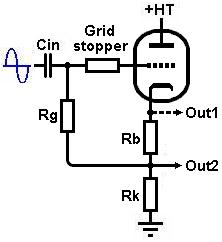
By adding a cap to the input (22nf), rb = 1k, rk = 47k taking the output from out2 through a 1uf cap you will turn the circuit into a less than unity buffer. I would also lower the grid stopper from 22k to about 300R.
A buffer is made from a cathode follower 99 percent of the time.
By adding a cap to the input (22nf), rb = 1k, rk = 47k taking the output from out2 through a 1uf cap you will turn the circuit into a less than unity buffer. I would also lower the grid stopper from 22k to about 300R.
Last edited:
It's rather hard to see what the circuit was actually designed for with only moderate gain and fairly high output resistance.
It looks like the front end of a power amplifier, the output would feed a phase splitter?
But it's already push-pull
It's two single ended grounded cathode amps in the same drawing, nothing push pull about it.
Buffers should have gain=1 (or thereabouts), high input impedance and low output impedance. This circuit has just one of those properties, therefore it is not a buffer.
It looks more like one of those circuits you find on a general circuit website, with a description something like "here is a useful/universal amplifier". It is useful in the sense that it has some gain; it is universal in the sense that it would be equally unsuitable for most amplification purposes.
It looks more like one of those circuits you find on a general circuit website, with a description something like "here is a useful/universal amplifier". It is useful in the sense that it has some gain; it is universal in the sense that it would be equally unsuitable for most amplification purposes.
- Status
- This old topic is closed. If you want to reopen this topic, contact a moderator using the "Report Post" button.
- Home
- Amplifiers
- Tubes / Valves
- Why is this a buffer?