> for old-school 600R headphones.
Old-school monitoring 'phones were 2K, so they could be bridged across a terminated 600 Ohm line (300 Ohms effective) without much loss.
This actually goes back before "audio". Telephone operator headsets were a few K impedance so they could connect across an in-use line without much drop of level. (Long ago, hang-up detection was dubious, and operators routinely listened-in at intervals to know when a call had ended.)
> for old-school 600R headphones.
Old-school monitoring 'phones were 2K, so they could be bridged across a terminated 600 Ohm line (300 Ohms effective) without much loss.
I was referring to genuine 600R headphones.
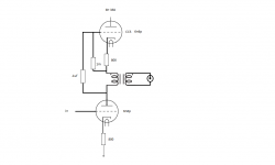
Does this seem like a place to start? I wonder about where to connect the CCS grid leak resistor and the cap? And also does the lower tube need a grid leak resistor as well?
The DCR of the transformer primary is 480 ohms. And the primary is 10k. The DCR is easy but does that mean the AC impedance is 10k? I was thinking of it as an SE amplifier with the CCS as more a part of the power supply?
The DCR of the transformer primary is 480 ohms. And the primary is 10k. The DCR is easy but does that mean the AC impedance is 10k? I was thinking of it as an SE amplifier with the CCS as more a part of the power supply?
Attachments
Last edited:
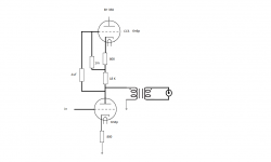
The above schematic may have a fatal flaw. I was intending to replace the plate resistor of the voltage amplifier with the transformer. The DC resistance is negligible. So it won't drop much voltage. I've been reading on the subject of AC resistance, inductance/ reactance and I thought it would provide enough impedance to allow gain. But I may be misunderstanding this in which case the signal will just ground through the power supply?
Kevin are you talking about post #25? And stocktrader200 are you talking about a lower knee in the high pass?
Also, to keep the voltage drop across the plate resistor to a minimum less current would be effective wouldn't it? The transformer has an 8.2/1 ratio. So with just a 25 volt swing at the primary I would have 3 volts out and the current would be multiplied by the same factor so it wouldn't take much current at all would it?
Also, to keep the voltage drop across the plate resistor to a minimum less current would be effective wouldn't it? The transformer has an 8.2/1 ratio. So with just a 25 volt swing at the primary I would have 3 volts out and the current would be multiplied by the same factor so it wouldn't take much current at all would it?
Kevin are you talking about post #25? <snip>
Yup, that's the one. The question to answer is how much audio potential is developed across the transformer given the way it is connected. (Clue this is also true with a resistor)
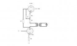
Better? But isn't the impedance of a transformer to AC greater than its DC resistance? In the attached will the tube see the parallel winding and the resistors as one? I mean a single ended transformer is the only thing between the plate of the output and the power supply?
Attachments
Last edited:
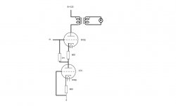
Hey guys, I broke my leg a couple weeks ago and have some new hardware in my right ankle. The upside is that I have some time! I made a new board for the CCS for the tubes. I now have all four tubes within .2 ma of each other with about 288 volts across each tube. The buzz I was hearing is somehow coming in on the input. I had to remove it from the first stage tubes to get the bias right.
So now I have to get rid of the damn buzz. The circuit was inputs to selector switch to volume control to first stage then second stage and finally AC coupled to the OPT primary.
My question is where is the best place to put the volume control? It's a 100k ALPS. I think its best to connect the switch directly to the first grid to start off. But should the volume control be between the tube stages? Or between the second stage and the OPT?
- Status
- This old topic is closed. If you want to reopen this topic, contact a moderator using the "Report Post" button.
- Home
- Amplifiers
- Tubes / Valves
- Inductor coupled Preamp