Crazy drive uses HV direct screen V drive, with a resistor from g2 to g1 (call that Rg2g1) and another resistor from grid1 to cathode (call that Rg1k).
The main drive is then via HV grid2 voltage drive, with grid1 acting as a current driven drive at low plate current, which compensates for gm2 being low at low plate current. The grid1 current drive saturates as plate current increases due to Rg2g1 and grid1 current dragging on it, while gm2 picks up with increased plate current and Vg2. The net effect is to get constant -total- gm drive of the tube. The resistor Rg2g1 is selected to get this compensation correct. Rg1k just acts as a pull down to help turn the tube off, but also affects the compensation some.
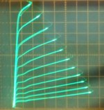
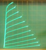
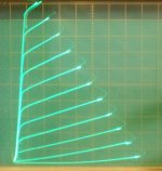
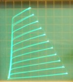
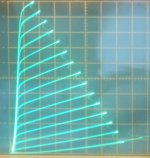
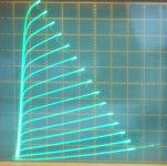
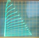
a) 26LX6 normal grid1 drive
b) 26LX6 grid2 only V drive
c) 26LX6 Crazy/Twin drive
d) 12HL7 Crazy/Twin drive
e) 40KG6 normal grid1 drive
f) 40KG6 grid2 only V drive
g) 40KG6 Crazy/Twin drive
The main drive is then via HV grid2 voltage drive, with grid1 acting as a current driven drive at low plate current, which compensates for gm2 being low at low plate current. The grid1 current drive saturates as plate current increases due to Rg2g1 and grid1 current dragging on it, while gm2 picks up with increased plate current and Vg2. The net effect is to get constant -total- gm drive of the tube. The resistor Rg2g1 is selected to get this compensation correct. Rg1k just acts as a pull down to help turn the tube off, but also affects the compensation some.
a) 26LX6 normal grid1 drive
b) 26LX6 grid2 only V drive
c) 26LX6 Crazy/Twin drive
d) 12HL7 Crazy/Twin drive
e) 40KG6 normal grid1 drive
f) 40KG6 grid2 only V drive
g) 40KG6 Crazy/Twin drive
Attachments
-
 rsz_26lx6_p.jpg51.4 KB · Views: 658
 -
 rsz_26lx6_g2_70_7vs.jpg66.9 KB · Views: 654
 -
 rsz_26lx6_crazydrive_55v_5,4vs.jpg71.9 KB · Views: 654
 -
 Crazy_TFH.JPG172.3 KB · Views: 648
 -
 rsz_40kg6_twin_3p5vst_888rg2g1_2770rg1k_50_50.jpg74.9 KB · Views: 69
 -
 rsz_40kg6_g2_5p5vst_50_50.jpg76 KB · Views: 59
 -
 rsz_40kg6_g1_1p5vst_78vg2_50_50.jpg82.9 KB · Views: 640
18GV8Single2W+2W
Not exactly Crazy Drive, due to CCS making the divider ratio 1:1 for G2/G1, relying only on G1 current (if any) to make the division. Interesting different project nonetheless, albeit with high global NFB.
Not exactly Crazy Drive, due to CCS making the divider ratio 1:1 for G2/G1, relying only on G1 current (if any) to make the division. Interesting different project nonetheless, albeit with high global NFB.
My crystal ball showed a message: ")
Since the diff input (2SJ109) forces the anode voltage to zero (input is ground referenced), I believe that the designer don't trusted to rely only on output trafo DCR for stabilizing the anode current. Is one of these complicated "exercise" projects...
Since the diff input (2SJ109) forces the anode voltage to zero (input is ground referenced), I believe that the designer don't trusted to rely only on output trafo DCR for stabilizing the anode current. Is one of these complicated "exercise" projects...
MJ^9510_(03)40KG6A-single-power-amp_SoyaS.pdf - Google Drive
Looks a lot like "crazy drive" published 10/1995 ...
Looks a lot like "crazy drive" published 10/1995 ...
Synola-509/Paravicini.pdf
Does this one count?
What part does the suppresaid play in this circuit? It is not tied to the cathode.
Does this one count?
What part does the suppresaid play in this circuit? It is not tied to the cathode.
Basically, but the devil are in details...MJ^9510_(03)40KG6A-single-power-amp_SoyaS.pdf - Google Drive
Looks a lot like "crazy drive" published 10/1995 ...
Dual Drive for sure, but:
The g1 DC bias is negative relative to cathode. This results in different transfer curve than both g1 and g2 being DC positive relative to cathode.
The AC signal will travel under these bias conditions.
For me (interpreting the gm curves from my test results) the gm curves for g1 negative and g2 positive resembled something like square law transfer (or higher!), and for g1 and g2 positive is closer to linear law gm.
Linear law is the key for Crazy Drive I suppose
Basically screen drive with a curious cathode bias (g1 is not signal driven).Synola-509/Paravicini.pdf
Does this one count?
What part does the suppresaid play in this circuit? It is not tied to the cathode.
The anode suppressor/compensation capacitors are tied to the feedback line.
Don't think so, both are just single drive albeit screen driven. No ac signal on g1.
Some Evidence of Crazy Drive Before WW2?
Referring to the Class B curves for the RCA 49, looks a lot like a pentode. Running in Class B as a zero bias triode was a way to get more audio out of a small tube. That was common in the 30s. The 49 data sheet is copied from the RCA/ Cunningham RC-11Tube Manual dated 1933. But the 49 & others like it had to be driven by a low mu triode thru an interstage transformer. The 6AC5GT is a very high mu audio triode that is normally driven by a low or medium mu triode by a direct connexion, not RC or IT. Several triodes were suitable as drivers.
The next step was put it all in one glass bottle. The 6B5 & 6N6G are the result. The symbol used for these tubes actually shews a driver triode direct connected to the included pentode. And the pinout plugs right into the socket of a corresponding pentode. So 6B5 subs for a 42 & 6N6G subs for a 6F6G. The resulting cct is self biasing, no cathode bias resister required. There are/were 25 volt heater versions as well. But tubes such as this never caught on.
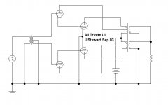
These tubes looked interesting in 2003 but very expensive. As an alternative any common audio power pentode when screen driven has a high mu. Turns out a 6F6 does well for the experiment. I drove the 6F6 with a 6SN7, both triodes in parallel. The results are in the attachment. The results also shew the driver triode plate can be used as a UL connexion to the OPT. Output is limited by plate dissipation just as it is in the normal hookup.
I went no further, many others had built amplifiers both SE & PP based on this principle. The all triode UL PP cct is a possibility for those with time to kill.
But it did lead to a convenient way to create pentode sub-circuits in Electronic Workbench software which come with not pentode models.
Not much new in toobz…………….or under the sun.
Some here on DIY have already seen a version of this a couple of years ago.Still looks like crazy drive to me!!
Referring to the Class B curves for the RCA 49, looks a lot like a pentode. Running in Class B as a zero bias triode was a way to get more audio out of a small tube. That was common in the 30s. The 49 data sheet is copied from the RCA/ Cunningham RC-11Tube Manual dated 1933. But the 49 & others like it had to be driven by a low mu triode thru an interstage transformer. The 6AC5GT is a very high mu audio triode that is normally driven by a low or medium mu triode by a direct connexion, not RC or IT. Several triodes were suitable as drivers.
The next step was put it all in one glass bottle. The 6B5 & 6N6G are the result. The symbol used for these tubes actually shews a driver triode direct connected to the included pentode. And the pinout plugs right into the socket of a corresponding pentode. So 6B5 subs for a 42 & 6N6G subs for a 6F6G. The resulting cct is self biasing, no cathode bias resister required. There are/were 25 volt heater versions as well. But tubes such as this never caught on.
These tubes looked interesting in 2003 but very expensive. As an alternative any common audio power pentode when screen driven has a high mu. Turns out a 6F6 does well for the experiment. I drove the 6F6 with a 6SN7, both triodes in parallel. The results are in the attachment. The results also shew the driver triode plate can be used as a UL connexion to the OPT. Output is limited by plate dissipation just as it is in the normal hookup.
I went no further, many others had built amplifiers both SE & PP based on this principle. The all triode UL PP cct is a possibility for those with time to kill.
But it did lead to a convenient way to create pentode sub-circuits in Electronic Workbench software which come with not pentode models.
Not much new in toobz…………….or under the sun.
Some here on DIY have already seen a version of this a couple of years ago.
Still looks like crazy drive to me!!Attachments
-
 Triode UL.jpg39.9 KB · Views: 176
 -
6AC5GT RCA.pdf105.1 KB · Views: 59
-
6N6G RCA.pdf39.5 KB · Views: 52
-
6B5 Tungsol.pdf64.3 KB · Views: 63
-
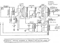 Rockolab PP 6B5 Amplifier 12W.jpg217.2 KB · Views: 168
 -
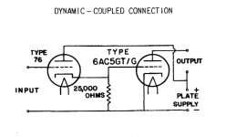 6AC5 SE Amplifier.jpg40.9 KB · Views: 138
 -
49 RCA 2.pdf67.3 KB · Views: 54
-
6SN7 6F6 Amp B.pdf13.2 KB · Views: 90
Crazy drive amp measurements
I’ve always been intrigued by the promise of crazy drive. There must be more that 100 pages devoted to it on this forum.
As far as I can tell however, only a couple of amps have been built with crazy drive output stages and nobody has published measurements or listening impressions.
I posted a question about my disappointing simulation results to this thread a couple of years ago.
I’ve been looking for an output stage for my tubelab Universal Driver Boards (UDB) so I thought I’d try some crazy drive experiments first.
These test results have been disappointing too.
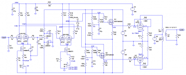
Schematic is shown below with 6HJ5 ouput tubes. I’m using a regulated 500V supply. No Schade or global feedback.
Crossover-wise the output stage seems to be happy at a quiescent current of 10mA or more. There’s a slight decrease in THD as the quiescent current is increased to 25mA.
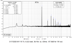
The first RTA plot is for 1kHz 1W and Iq of 25mA. Rg2g1 is 2.2k for this measurement.
I tried Rg2g1 from 1.2k to 3k. There was a slight decrease in THD but not a lot.
I also a tried a 4 load but once the power level was adjusted to 1W THD was still disappointing.
Just to be sure I measured the THD at the source of Q1. No problem there as you can see in the second plot.
So, where is this straight wire with gain?
Am I missing something or is this the reason lots of crazy drive amps haven’t been built?
I’ve always been intrigued by the promise of crazy drive. There must be more that 100 pages devoted to it on this forum.
As far as I can tell however, only a couple of amps have been built with crazy drive output stages and nobody has published measurements or listening impressions.
I posted a question about my disappointing simulation results to this thread a couple of years ago.
I’ve been looking for an output stage for my tubelab Universal Driver Boards (UDB) so I thought I’d try some crazy drive experiments first.
These test results have been disappointing too.
Schematic is shown below with 6HJ5 ouput tubes. I’m using a regulated 500V supply. No Schade or global feedback.
Crossover-wise the output stage seems to be happy at a quiescent current of 10mA or more. There’s a slight decrease in THD as the quiescent current is increased to 25mA.
The first RTA plot is for 1kHz 1W and Iq of 25mA. Rg2g1 is 2.2k for this measurement.
I tried Rg2g1 from 1.2k to 3k. There was a slight decrease in THD but not a lot.
I also a tried a 4 load but once the power level was adjusted to 1W THD was still disappointing.
Just to be sure I measured the THD at the source of Q1. No problem there as you can see in the second plot.
So, where is this straight wire with gain?
Am I missing something or is this the reason lots of crazy drive amps haven’t been built?
Attachments
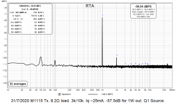
Iq measurements
Higher power will have to wait until I put a big old transformer back in. I'm only using a puny transformer for 1W testing.
It'll run quite happily down to an Iq of 5mA. Distortion increases below that.
Iq THD
1.5mA 9.45%
2.5mA 5.21%
5mA 1.43%
25mA 1.51%
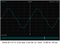
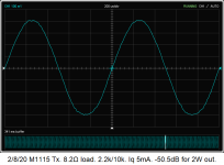
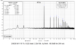
REW scope shots for Iq 1.5mA and 5mA. RTA for Iq 5mA and 2W output.
What does distortion do as you increase power? Have you tried very low bias current or does crossover distortion become a problem? Would be good to see some scope shots (even the scope in REW might be useful)
Higher power will have to wait until I put a big old transformer back in. I'm only using a puny transformer for 1W testing.
It'll run quite happily down to an Iq of 5mA. Distortion increases below that.
Iq THD
1.5mA 9.45%
2.5mA 5.21%
5mA 1.43%
25mA 1.51%
REW scope shots for Iq 1.5mA and 5mA. RTA for Iq 5mA and 2W output.
Attachments
The 1.5mA plot clearly shows the increase if THD above about 1.5% is contribution in the form of crossover glitches.
The 5mA plot looks alright, I'm not sure I'd pay to much credence to the small wiggles (you wouldn't see that on plenty of CRT scopes)
They could be some small resonances being excited in the OPT, but I haven't seen them when testing with a sine.
If you test with square or pulse waveform they will pop right out.
Where's that noise = 1.77% coming from? Doesn't make any sense...
You're right. It doesn't make any sense. The 500V and ±150V are all clean on the scope at least.
I'm using Pete Millett's Soundcard Interface and it's perfect in loopback mode.
Higher Power Measurements (sort of)
The line matching transformer was scavenged from my first valve amp build, a Silicon Chip Currawong, that I was never able to get rid of 50Hz/100Hz noise from. Fortunately, I’ve built and modified much more successful valve amps since then!
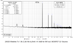
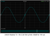
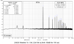
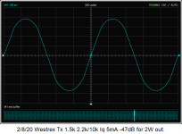
Anyway, I’ve replaced that transformer with a borrowed Westrex C4779 that’s probably older than me. It’s currently wired for 12Ω but my measurements suggest 1.5k plate-to-plate for 8Ω. I may need to wire it for something higher than 1.5k.
The first 2 screen shots are 1W. THD is actually worse than the little line matching transformer.
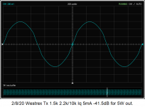
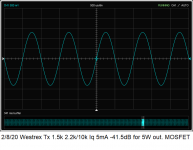
The 3rd and 4th screenshots are for 2W. The waveform is obviously distorted.
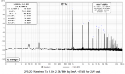
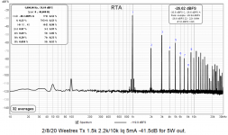
The 5th and 6th screenshots are for 5W. Seriously distorted.
The 7th and 8th screenshots show the waveform and RTA at the source of one of the MOSFETs so the problem is in the output stage.
I’ll try the screen drive only tomorrow.
The line matching transformer was scavenged from my first valve amp build, a Silicon Chip Currawong, that I was never able to get rid of 50Hz/100Hz noise from. Fortunately, I’ve built and modified much more successful valve amps since then!
Anyway, I’ve replaced that transformer with a borrowed Westrex C4779 that’s probably older than me. It’s currently wired for 12Ω but my measurements suggest 1.5k plate-to-plate for 8Ω. I may need to wire it for something higher than 1.5k.
The first 2 screen shots are 1W. THD is actually worse than the little line matching transformer.
The 3rd and 4th screenshots are for 2W. The waveform is obviously distorted.
The 5th and 6th screenshots are for 5W. Seriously distorted.
The 7th and 8th screenshots show the waveform and RTA at the source of one of the MOSFETs so the problem is in the output stage.
I’ll try the screen drive only tomorrow.
Attachments
-
 Q1 Source RTA 5W.png72.2 KB · Views: 57
 -
 Westrex scope 1W.png39.2 KB · Views: 53
 -
 Westrex RTA 1W.png65.2 KB · Views: 52
 -
 Westrex scope 2W.png41.1 KB · Views: 54
 -
 Westrex RTA 2W.png72.8 KB · Views: 59
 -
 Westrex scope 5W.png41.1 KB · Views: 55
 -
 Westrex RTA 5W.png75.1 KB · Views: 58
 -
 Q1 Source scope 5W.png46.4 KB · Views: 57
Are you 100% that it not something else distorting?
The 1st shot has some asymmetry and I guess 2nd Harmonic dominating.
But the 5W shot looks all symmetrical and nice, the FFT looks awful.
I agree with your assessment.
When I got my first OPTs, that I thought were half decent, I was a little miffed when the THD result was not as good as some line matches I had tested with.
These line matches did load at the reflected impedance I wanted, but only at 1-2kHz, an octave lower, and the impedance was probably 35% down, causing THD to increase.
An interesting test, I took reading for a single test, FFTs of both the primary signal, and secondary signal.
My observations have been that some harmonics are attenuated, and others amplified, and what looked quite good primary side, or often far better on the secondary side. If not better, one trades lower 3rd for higher 2nd, or vice versa.
Last edited:
- Status
- This old topic is closed. If you want to reopen this topic, contact a moderator using the "Report Post" button.
- Home
- Amplifiers
- Tubes / Valves
- More Ruminations on Screen Drive/Crazy Drive