"what do you think is a better choice?"
That would depend on the operating mode.
For triode mode, a higher primary Z, and higher B+, will give less distortion and lower Zout. But the OT may be a problem if the Zpri has to be too high. High B+ gets expensive too. Somewhat of a waste to use a high current rated tube at really low current (still paying for the heater current). And trioded TV Sweeps are not friendly about HV on g2 (runaway).
For normal pentode mode, too low a Zpri, with low B+, will lead to a load line with significant variation in gm, so higher distortion. Some moderate Zpri will have an optimum/minimum (typically a broad optimum) in distortion. And a high primary Z will again develop distortion from the curvature of the plate curves from screen grid distortion effects. One can plot some load lines on the usual plate curves to find an optimum range.
G2 drive seems to get rid of most of the screen grid distortion from the plate curves (notice lack of kinks below, 3rd pic), so there would be an advantage to use a higher B+ and higher Zpri OT for lower dist., since that would also require less +Vscreen drive to develop the current. Up till the OT becomes an issue anyway.
UL mode is similar to pentode, an optimum range for Zpri and B+. Tough to get good curves to work with though. Tube reliability an issue with UL or triode mode'd pentodes with HV on g2. (runaway)
Crazy/Twin Drive has such uniform curves that there likely isn't much variation in distortion with Zpri. Maybe just a little improvement with higher Zpri. I would place the emphasis here on OT performance and B+ supply economy. So tilting toward lower B+ and lower Zpri. However, a higher Zpri would help with the Zout issue, but local/global N Fdbk can fix that easily too.
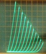
Some 36LW6 Sweep tube curves below to illustrate each:
Triode,
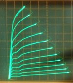
Pentode,
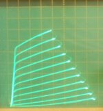
g2 drive,
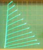
Crazy/Twin drive
That would depend on the operating mode.
For triode mode, a higher primary Z, and higher B+, will give less distortion and lower Zout. But the OT may be a problem if the Zpri has to be too high. High B+ gets expensive too. Somewhat of a waste to use a high current rated tube at really low current (still paying for the heater current). And trioded TV Sweeps are not friendly about HV on g2 (runaway).
For normal pentode mode, too low a Zpri, with low B+, will lead to a load line with significant variation in gm, so higher distortion. Some moderate Zpri will have an optimum/minimum (typically a broad optimum) in distortion. And a high primary Z will again develop distortion from the curvature of the plate curves from screen grid distortion effects. One can plot some load lines on the usual plate curves to find an optimum range.
G2 drive seems to get rid of most of the screen grid distortion from the plate curves (notice lack of kinks below, 3rd pic), so there would be an advantage to use a higher B+ and higher Zpri OT for lower dist., since that would also require less +Vscreen drive to develop the current. Up till the OT becomes an issue anyway.
UL mode is similar to pentode, an optimum range for Zpri and B+. Tough to get good curves to work with though. Tube reliability an issue with UL or triode mode'd pentodes with HV on g2. (runaway)
Crazy/Twin Drive has such uniform curves that there likely isn't much variation in distortion with Zpri. Maybe just a little improvement with higher Zpri. I would place the emphasis here on OT performance and B+ supply economy. So tilting toward lower B+ and lower Zpri. However, a higher Zpri would help with the Zout issue, but local/global N Fdbk can fix that easily too.
Some 36LW6 Sweep tube curves below to illustrate each:
Triode,
Pentode,
g2 drive,
Crazy/Twin drive
Attachments
Last edited:
"are there other considerations we need to look at?"
One thing that has not been investigated very well is the P-P crossover region (biasing, idle current) for Crazy/Twin Drive. (SE should be fine) The uniform gm versus plate current would produce gm doubling around crossover if operated at the usual idle currents for P-P in g1 pentode mode. This is not too surprising, since g2 drive also likes to be operated with lower idle current. (Crazy/Twin is really just a compensated linearity g2 drive variant)
Assuming the gm does eventually taper off at very low plate current, for a smooth overlap with the other P-P tube (and it looks like this is the case on the curve tracer), then efficient operation will be possible. Allowing higher power output (similar to g2 drive). Satisfactory crossover needs to be confirmed with an FFT analyzer while adjusting the bias/idle.
A smaller concern would be heating of the grid 1 with the positive V excursion. This looks like it can be quite minimal and still achieve linearization of the g2 drive. Not too worried about this (except for someone adjusting Rg2g1 too low during testing). Just would be nice to get some extended operation results. Would be nice to see a confirmation that Rg2g1 can be a fixed value over the tube life. And that there are no tube runaway issues. Reliability likely will be somewhat better than g2 only drive, since the g2 drive voltage can be around 25% lower with the g1 assist.
Then, of course, there is the high output Z issue. This is a well known and fixable problem with pentode mode, just a bit more challenge to incorporate local N Fdbk schemes into a HV driver stage.
And then there is the driver stage, it has to drive this with g2 like voltages and currents. This may be the biggest issue in the end. Fortunately the g1 assist, along with the low internal Mu of TV Sweeps makes this manageable.
..
Last edited:
SE operation is class A, so this P-P mode will be much lower idle current than that.
It will be even lower than typical g2 drive (which is nearly class B bias'd already), since the tube gm is held constant down to rather low current with Crazy/Twin. You -might- be looking at just 10 mA of idle current for good crossover! Maybe Mickeystan has some input on this with his amp.
To make a wild guess, g1 is what is maintaining the gm at low current, and it has around 3 or 4 X the gm of grid 2. So it should be able to maintain the same gm as grid 2 at around 1/2 to 1/3 the current of a typical g2 drive Amp's idle current.
So I'll make a Scientific Wild A_s Guess that we should see optimum idle current about 1/2 of a similar g2 only drive amp. An FFT will give the final opinion however.
There might be some advantage to allowing some small gm doubling, with a little more idle current, to overcome the low permeability of usual OT steel at low signal levels. Then let the N Feedback smooth the whole thing out. Just some idle thinking....
..
Last edited:
3 mA ehh!
Well 800V is a bit more than I would call practical B+. My bench supply only goes to 600V. Maybe at 450V we'll see about twice that, so 5.3 mA for g2 drive. Then 1/2 that for Crazy/Twin drive, 2.66 mA.
The race is on!
How LOW can you GO.
Let's see. 2.66 mA at 450V would be 1.2 Tube Watts at idle.
One may have to put an electric heater behind the amplifier to simulate a tube amp.
It's very counter intuitive to think of running these tubes at a low bias although that seems t be what they were designed to do. Coming from Nelson Pass, SS, Class A designs, I always tend toward Class A. I have always found b/AB amps to sound thin and lifeless in the midrange even if they had gobbs of dynamic power.
I am starting a new thread today, posting loadlines and such. Please visit and critic/educate. It would be of great help.
SmokingAmp, Am I correct in thinking the first traceline in these 6hj5 measurements are the 0V line?
SmokingAmp, Am I correct in thinking the first traceline in these 6hj5 measurements are the 0V line?
Last edited:
"Am I correct in thinking the first traceline in these 6hj5 measurements are the 0V line?"
Yes, I generally try to set the curve tracer up that way, with g1 = 0 V for the high current left or top curve. There might be a few graphs from way back, when I first got the curve tracer, where I didn't have that feature implemented yet. (was still learning)
Generally for these Sweep tube graphs, the Vertical scale is 50 mA/div and the horizontal scale is 50V/div. For the Sweep tube triode curves, usually around 7 V steps on grid 1, since that's the most I can currently get from the tracer. Later plots, I have tried to include the V step size and g2 Volts in the title too.
That thin sounding effect usually seen in class aB and class B is from less (total) gm near crossover. Tubes and Mosfets develop more transconductance at higher currents. N Fdbk in some form is typically relied upon to smooth everything out then.
Crazy/Twin drive appears to hold near constant gm throughout the current range, except very near to P-P crossover, so that issue hopefully will be improved here. But beware that pushing the idle current up excessively will cause definite gm doubling in the overlap region with this scheme. You likely won't see a continuing improvement in crossover with higher idle current, as typically seen with the usual P-P approaches.
One -could- run P-P Twin drive in class A for the most linear tube amp ever, but the efficiency gains will be totally lost. A space heater for sure.
OTL using Twin Drive might be interesting, avoiding the huge idle heat dissipation in near class B. But then there are still all those big heater Watts for a bank of Sweep tubes.
..
Last edited:
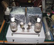
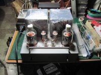
Hello everyone, I have not been playing with my crazy drive/twin drive amp lately as I have been running an AB2 triode amp I built with KT66 wired as triodes for the output stage. Since everyone was talking about idle currents and twin drive I thought I would quickly connect my twin drive up and see where I left it with regards to idle current. The amplifier still sounds very good to me and it is idling at 8ma per 6DQ5 output tube. Just for the fun of it I hooked up my 475 scope and looked at the cross over distortion and really could not see one. I then cranked the bias down to 4ma per tube and could see some onset of cross over distortion. As fall turns to winter here in Oregon, I will probably play some more with the amplifier during the months to come. I would encourage others to play with twin drive and share their results. I spent next to nothing building this amplifier as I had more than 90% of the parts needed in my collection. Its been fun playing with something different. I thank Smoking Amp for the inspiration to play with this output stage driving scheme as his graphs of crazy drive performance of sweep tubes were just too irresistible! I would also like for people to know that since my old original schematic was posted, I did change the bias adjusting scheme to achieve the ability to turn the current down lower in the output stage. Thus, the original schematic is out of date. Mickeystan
Thanks greatly, Mickeystan!
I think we can all settle for just 8 mA of idle current. This is way below the usual class AB g1 pentode idle current. I think we can all feel relieved that crossover can be handled well with the new scheme.
Do you see any hint of gm doubling above the 8 mA, maybe at 16 to 20 mA or so? Or, to put it differently, does any new squiggle in the crossover appear somewhere above the 8 mA level.
Last edited:
Smoking Amp, I took a quick look earlier today at the crossover performance at 4 ma, 8 ma and 17 ma of cathode current on the 6DQ5 output tubes. The only setting I saw any squiggle (distortion to the crossover region) was at 4 ma. Since the amplifier is still up on the bench, I will take a closer look and measure the actual distortion 1 khz and 1 watt of output at all three levels and share the results. More to come..... Mickeystan
Ray, I will be happy to re-post the schematic. Before I do, I want to check it out again against the amplifier since I know I have changed the bias scheme. Tomorrow, I will take a better look at several bias levels while measuring the distortion levels. As I do this, I will take the time to recheck the schematic and update it as necessary before I put it up to share. Mickeystan
Hello everyone, This message is a follow up I promised to do with regards to my Crazy/Twin drive 6DQ5 sweep tube amplifier. Today, I took a closer look at the output waveform into a non reactive 8 ohm resistance load, at various output stage idle currents while measuring distortion today. I did this using a Wavetek 182a generator and a HP 334 distortion analyzer. The as built amplifier schematic is also attached. The results I obtained are listed below, (all were taken at 1 watt rms output at 1khz);
5 ma cathode idle current per output tube 0.44% distortion
8 ma cathode idle current per output tube 0.40% distortion
12 ma cathode idle current per output tube 0.21% distortion
20 ma cathode idle current per output tube 0.16% distortion
24 ma cathode idle current per output tube 0.23% distortion
28 ma cathode idle current per output tube 0.30% distortion
In my earlier post the other day, I thought I could see a slight deformation in the cross over distortion at 4 ma idle current. After taking a closer look, I truly cannot say I see any form of crossover distortion. It seems that 20 ma of idle current is what the amplifier wants and it will make 50 vpp output when cranked up without any significant distortion to the sine wave output. Thus, it will deliver approx. 40 watts rms into a 8 ohm load.
I have listened to the amplifier at various idle current levels and have not noted it sounding any different at any of them. This amplifier sounds very good to me and I am pleased with it. I do not attempt to describe in detail how wonderful a amplifier sounds. Unlike most people, I use a preamp ahead of all my amplifiers to boost the high frequencies as my hearing is significantly damaged above 4 khz. I hope this feedback is useful to folks. Mickeystan
Attachments
- Status
- This old topic is closed. If you want to reopen this topic, contact a moderator using the "Report Post" button.
- Home
- Amplifiers
- Tubes / Valves
- More Ruminations on Screen Drive/Crazy Drive