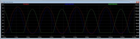
dch53 has previously posted distortion spectra for the signal from the drivers (source followers) showing that the cause of the output stage distortion was not from there. The gm doubling I've been talking about can be seen in this simulation trend attached. Because crazy drive makes each tube a constant gm device (except for at very low currents), when both tubes are operating you have twice the gm of a single tube which can be seen in the increased slope in the output signal in the crossover region.
At low output levels when operating in class A you don't see it, and at high output levels it shows up as a small glitch at the zero crossing point. In between it can result in very high distortion.
At low output levels when operating in class A you don't see it, and at high output levels it shows up as a small glitch at the zero crossing point. In between it can result in very high distortion.
Attachments
Yes, I think you have it there. The idle current with Crazy Drive needs to be set much lower than typically set for class aB, but not so low as to cause a crossover distortion notch. Very fine and stable tuning of idle current may be required for class aB P-P.
Then there is the issue of high output Z (without using local or global N Fdbk anyway)
---------------------------------------------------------------------------
The latest development with Crazy Drive is to use it as the Shunt Schade-like local N Fdbk network, instead of the drive network.
Then drive the tube's cathode instead. Not only linearly spaced plate curves (triode like, low Z) but straight line triode curves.
Here is an early example (not using a Mosfet follower for the screen grid yet), better (higher gain or Mu) are possible with a Mosfet follower on g2.
This is more like the "straight wire with gain" sought after. Low and constant output Z. But will still have similar bias related gm doubling problems in P-P class aB.
Attachments
Last edited:
Smoking-amp, I am having trouble visualizing a Shunt Schade-like local negative feedback network driving the tube's cathode with a Mosfet follower on g2.
Would you please direct me to a schematic of this arrangement, or post a schematic? Thank you.
There are 3 links at post #229 that might help.
I am having trouble visualizing a Shunt Schade-like local negative feedback network ......
Unfortunately my scanner has died recently, but I will get a new one soon.
Best way to look at this is the original Crazy Drive resistor network (Rg2g1 from grid 2 to grid 1, and Rg1K from grid 1 to a ground ref. in this case)
Now put an N channel Mosfet follower in front of the grid 2 terminal to handle g2 current. So the Mosfet follower gate will be a high Z point driving the voltage on g2.
Then we put in a "Shunt Schade" R divider network from plate to an AC ground reference ( some DC level there to set the idle g2 voltage), with the mid point connected to the Mosfet follower gate for g2 control. (protection zener and gate stopper R around the Mosfet as usual ) So the N Fdbk signal now sets the g2 voltage. (and some linearising influence on grid 1 thru the Crazy network besides)
Now, to drive this thing, we use a P channel Mosfet follower below the tube cathode. Source terminal to cathode. Input signal at the gate with DC bias V.
Input signal sets the cathode V, and since cathode V to the g2/g1 complex sets the tube current in a linear way, we end up with a linear tube with linear N Fdbk. Resulting in a -very- linear "triode". No curvature even in the triode curves and equal spacing versus input V.
-------------------------------------------------
Now this scenario can be generalized further. Suppose we connect the plate to g2 directly. Then the g2 Mosfet follower can be dispensed with, but the Crazy Fdbk network to g1 stays in place. We end up with a linearized triode. In fact, even just a normal triode could be used now with the linearization network added. (but still needing cathode input drive)
One can play with the Crazy Fdbk network resistors (particularly Rg2g1) to control just how much linearization one wants to add. So on can take a "poor" triode (high 2nd harmonic) and adjust it's characteristics upward toward 300B or further to a 211 triode or anything in between.
A Sweep tube can be used obviously too (original case), although one will generally want to lower the g2 voltage below the plate V typically for safety of the tube. So the g2 follower N Mosfet will be needed typically.
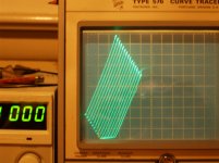
For just a little V drop, one could put a resistor directly between plate and g2 (as done for the curve trace above) (and an additional resistor from g2 to AC Gnd reference is needed to form the Fdbk divider) ( then the Rg2g1 Crazy resistors etc. for linearizing). That 1st top resistor will have to carry screen current besides N Fdbk current, so will get hot if much V drop is used.
(putting a Zener in instead will cause the Mu factor to change with plate voltage, probably not what is intended)
One can also dispense with the Crazy Fdbk network if one wants linear triode curves, but with the usual diode conduction plate curves. Just take a triode and put the usual "Shunt Schade" N Fdbk network in, back to grid 1. (R divider between plate or UL tap and Gnd reference, with mid point to grid 1) Then driven at the cathode by the P channel Mosfet follower.
Side Note:
Experimenting with this to get the above curve traces, confirmed a long held belief that screen current would look linear resistive if the screen V is kept at a constant fraction of plate V. The screen intercepts a constant fraction of plate current if screen V is a constant fraction of plate V. Proportional
V and I gives you a constant resistor. This is probably only glancingly useful for the Crazy Fdbk scheme above, but is useful to know for an unusual N feedback scheme to the driver tube screen grids. First time I saw it used was by Jan Vieset for a multi-loop feedback design. By arranging the driver gain correctly, the N Fdbk (from a P-P OT primary or UL taps) can drive the driver screen grids with a constant fraction of the driver plate output V. So no follower Mosfets are needed to operate the driver screens. Could prove useful in other cases, who knows.
Last edited:
The gm doubling I've been talking about can be seen in this simulation trend attached. Because crazy drive makes each tube a constant gm device (except for at very low currents), when both tubes are operating you have twice the gm of a single tube which can be seen in the increased slope in the output signal in the crossover region.
This is one of those things that once you see, you can't un-see. It's especially apparent in the second screenshot of post #238.
- Status
- This old topic is closed. If you want to reopen this topic, contact a moderator using the "Report Post" button.
- Home
- Amplifiers
- Tubes / Valves
- More Ruminations on Screen Drive/Crazy Drive