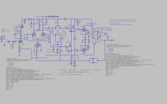
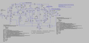
It's an LTSpice file. Thanks Mickeystan.
Here is a link to the earlier schematic in .jpg form:
http://www.diyaudio.com/forums/tube...nificent-television-tubes-67.html#post4675905
and attached below is the new schematic in .jpg form:
Here is a link to the earlier schematic in .jpg form:
http://www.diyaudio.com/forums/tube...nificent-television-tubes-67.html#post4675905
and attached below is the new schematic in .jpg form:
Attachments
Last edited:
With the higher idle current now, I wonder if this is a characteristic of the 6DQ5 or of Crazy/Twin Drive.
It would be interesting to remove the Rg2g1 resistors and see where the g2 only drive is optimally biased.
(Or just put clip leads across the Rg1k resistors. No de-soldering needed then.)
It would be interesting to remove the Rg2g1 resistors and see where the g2 only drive is optimally biased.
(Or just put clip leads across the Rg1k resistors. No de-soldering needed then.)
Last edited:
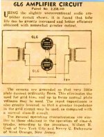
") THX for the cct schema. For the curious & others here is the original patent on the screen drive pentode copied from an old copy of one of the magazines popular in the day. Would be around 1955 I think. A bit fuzzy, but readable.
THX for the cct schema. For the curious & others here is the original patent on the screen drive pentode copied from an old copy of one of the magazines popular in the day. Would be around 1955 I think. A bit fuzzy, but readable.What is the measured DF of the resulting amplifier?
Attachments
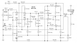
And here is David Berning's nearly identical patent dated 1976. Tube amplifiers for high-end audio by The David Berning Company Now that it's expired who else is going to patent screen drive? Crazy / Twin drive maybe?here is the original patent on the screen drive pentode
NOT!
What is the measured DF of the resulting amplifier?
My screen drive experiments revealed a DF / output impedance similar to the same tube driven by G1. The usual NFB methods can improve things.
divided down signal being fed into g2? Is it possible to schade g2?
All of the drive goes to G2, the divided down version goes to G1. The divider ratio is tube dependent.
I have tried Schade feedback on a Twin Drive push pull design. There are several places to insert the feedback signal from the output tube plate. The driver plate, driver cathode, and G1 are the easiest. With a couple of added resistors the mosfet gate is another choice. Since G2 is directly fed by a low impedance mosfet source, feedback applied here will largely be ignored.
My experiments have not found a universal "best choice." Each can result in some instability especially with high Gm tubes and crummy asymmetrical OPT's due to phase shift at ultrasonic frequencies.
I believe TubeMania posted it, and I posted a mention about my PL509 amplifier, with 300V +B and ~100mA iq, 105Vg2, for a load of 1k9. Plenty of class A for the moderate sensitive Troel's TQWT and some >60W for music with high dynamic range peaks. Pentode connected with some cathode feedback.someone posted a pp el509 with had an output of 80 wats at a B+ of just around 300+ volts maybe a couple of years back.......
Tube Mania amp has more power even with UL, thanks to higher Vg2. Anode loadline is same, 1k9.
60W with one pair with only 300V B+ is a byproduct of huge cathodes
but I admit that my choosen loadline and Vg2 bias is a "accident" (not optimized) Calculated in a hurry, but works. A little more Vg2 and I can reach the 80W, probably...I noted this in practice with my PL509 amp. To be fair, with low power (like <10W or so), the distortion is low, interesting low. But when the PL's are approaching saturation, the distortion skyrockets, with some power into 6% THD (the "last 10W's", aka >45~50W towards "max power").<snip>
For normal pentode mode, too low a Zpri, with low B+, will lead to a load line with significant variation in gm, so higher distortion. Some moderate Zpri will have an optimum/minimum (typically a broad optimum) in distortion. And a high primary Z will again develop distortion from the curvature of the plate curves from screen grid distortion effects. One can plot some load lines on the usual plate curves to find an optimum range.
<snip>
Interesting is that the choosen 1k9 loadline has proved to reduce this effect.
Completely distinct for eg. 6EM5, a "conventional" vertical sweep tube, operating like a conventional audio tube, starts saturating with only 1% THD (or less!), like stated in manuals for some audio tube types. Also have a sweet spot but is more linear tha the PL in this situation.
And here is David Berning's nearly identical patent dated 1976.
Tube amplifiers for high-end audio by The David Berning Company
-----------------------------------------------------------------------------
Amazing what gets patented even tho there is plenty of evidence of prior art. I recall reading a report perhaps 25-30 years ago how someone had managed to patent the CF!! Hard to believe.
Attachments

"...if someone have a idea about correct g1/g2 ratio for PL509"
I don't have a PL509 or 6KG6 here to test on the curve tracer for Crazy/Twin Drive currently.
I did look back through some tubes that were tested (with a similar internal Mu to 6KG6). Rg2g1 seems to vary between 1.4K and 3.7K while Rg1k varies between 700 and 2000 Ohms. Typically about a 2 to 1 ratio between Rg2g1 and Rg1k.
I would just start out with 2.2K Ohms Rg2g1 and 1.1K Rg1k for ball-park starters for the PL509. The values are not real critical at all. Check post 678 in this thread for a typical tune up session. If you try the adjustable pot method (like 5K) for adjusting Rg2g1, I recommend putting a 1K resistor in series to prevent over currenting grid 1. Rg1k at half that value should work OK, but you could try a pot for that too. You will want some curve tracer method (like the uTracer) or an FFT sound card test (in a SE circuit) to select the optimum values.
Gee, the R values for the various tubes I tested earlier are scattered around and sometimes hidden in the commentary. Or missing. I need to go back through my Sweep tube collection and test them all on the curve tracer again and post a table of reasonable R values. When time allows.
..
Last edited:
two more tube grid exponents (g1, g2):
6AV5/6BQ6 2.13 1.34
6LU8/6LR8 (pent) 2.65 1.35
Two resistors get added, Rg2g1 from g2 to g1, and Rg1k from g1 to cathode. An LED or two may get inserted in series with Rg1k in some cases to provide a small offset voltage (drop) to linearize the low current range of the tube. (not always required)
The results have been remarkable to say the least. A straight wire with gain.
Although the g2 drive curves here for the 6AV5/12BQ6/12GE5.... are pretty good already (low gm for g2). Other tubes (high gm for g2) have more obvious 2nd harmonic dist. which gets fixed cleanly by the special drive. (see earlier pics)
------------------------------------------
I didn't have a 6AV5 around handy, but I do have some 12BQ6GA tubes. The older style 12BQ6GA is most likely equivalent to the 6AV5. The newer style 12BQ6GA is pretty clearly equivalent to the 6JN6/6JM6/6GE5/6FW5/6GV5/6DQ6B series.
All pics are 20 mA/div Vert., 50V/div Horiz. (yeah, these are all well over the max. plate dissipation for these little sweeps, but they can take it.) (the -g1 drive comparison pics might be 50 mA/div Vert., I don't have the data from these older pics.)
1) 12BQ6GA (old style) g2 drive, 95V max g2, 7V steps
2) 12BQ6GA (old style) special drive, 50V max g2, 3.5V steps
3) 12BQ6GA (new style) g2 drive, 82V max g2, 7V steps
4) 12BQ6GA (new style) special drive, 45V max g2, 3.5V steps
5) 12BQ6GA (old or new style? was an old pic) conventional -g1 drive (for comparison)
6) 12GE5 g2 drive, 84V max g2, 7V steps
7) 12GE5 special drive, 35V max g2, 3.5V steps
8) 12GE5 conventional -g1 drive (for comparison)
The Rg2g1 for the 12BQ6GA (new) and for the 12GE5 was 2.17K Ohms
and Rg1k for both was 1.04K Ohms. No LV offset voltage was used for Rg1k for these.
so, i tie the cathode to ground (through an 1R to measure current?), grid to the junction between the rg2g1/rg1k resistors, bottom of the rg1k to my negative rail, or to ground directly? would i adjust for idle current of the sweep tube, at the gate of the follower that feeds the grids?
I'm thinking of trying out some 2200R, and 1500R, and tying the bottom of the stack to a negataive voltage from around 24 volts or so. Would this work, or would these values be too small? These would be driven by either a mosfet follower, small pentode, or maybe a triode. what would be a good current to idle through the resistors? would high wattage resistors be necessary?
The 6/12BQ6GA got tested here somewhere. Should be similar/exact R values to the 6/12AV5. Close enough for starters.
You can always use a 5K pot for the Rg2g1 and adjust to find the best spot with a PC sound card FFT display (attenuate input to the sound card safely, 1V, AC power isolated). (use a series 1000 Ohm R with the pot, so as to not over current grid 1) Use the same Rg1k resistor as the 12BQ6 for starters, its not as critical.
Do you mean to replace the G1 resistor (that feeds down to the negative supply) with the pot? would i tie one end of the pot to the wiper, or just tie it to G1?
Sorry if i seem dense, I've been following this thread off and on for a couple years, and finally want to actually build up a proof of concept and get going on actually wiring up a sweep amp lol.
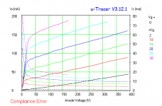
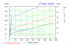
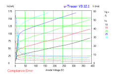
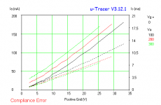
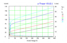
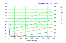
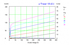
Some tracer results...
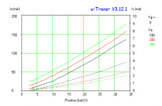
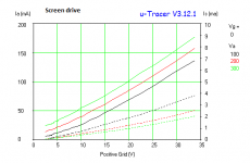
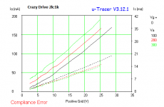
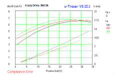
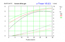
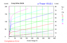
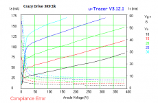
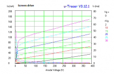
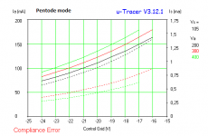
Here is some testings I made, using G2 only, Crazy Drive with 3k9:1k resistors, Crazy Drive with 2k:1k resistors and triode mode
OOPS.: I forget to include infos; the attachments don't show the archive name (the explanation of connections are in archive's names)
Soon I publish with the additional infos
Attachments
-
 PL509 2k-1k 2.png13.6 KB · Views: 82
 -
 PL509 2k-1k 1.png11.5 KB · Views: 94
 -
 PL509 2k-1k.png13.9 KB · Views: 85
 -
 PL509 3k9-1k.png13.7 KB · Views: 95
 -
 PL509 3k9-1k 1.png11.7 KB · Views: 93
 -
 PL509 G2 only.png13 KB · Views: 497
 -
 PL509 G2 only 3.png12.9 KB · Views: 513
 -
 PL509 G2 only 2.png12.4 KB · Views: 517
 -
 PL509 G2 only 1.png11.3 KB · Views: 513
 -
 PL509 triode 2.jpg25.5 KB · Views: 109
Last edited:
Now with explanations ...
...and better organized
...and better organized
Attachments
-
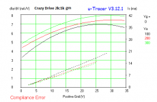 PL509 2k-1k gm.png9.8 KB · Views: 112
 -
 PL509 G2 only 1.png9.4 KB · Views: 115
 -
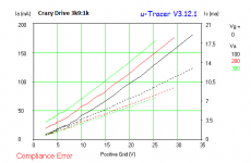 PL509 3k9-1k 1.png9.9 KB · Views: 104
 -
 PL509 2k-1k 1.png9.3 KB · Views: 100
 -
 PL509 3k9-1k gm.png9.8 KB · Views: 101
 -
 PL509 G2 only gm.png9.2 KB · Views: 123
 -
 PL509 triode 2.jpg25.5 KB · Views: 129
 -
 PL509 2k-1k 2.png11.9 KB · Views: 127
 -
 PL509 3k9-1k.png11.8 KB · Views: 139
 -
 PL509 G2 only 3.png11.1 KB · Views: 150
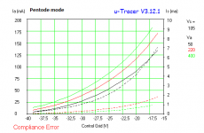
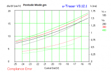
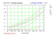
Some conclusions from this...
Yes, a considerable less voltage drive for Crazy Drive, but this also confirm the necessity to use a negative supply, unless one can copy the JVC and Super-A idea (a biasing scheme to "lock" the minimum current in bipolar output transistors, to avoid the resulting minority carrier delay provoked by cut-off). Of course, the "residual" current in PL509 G2-derived drive is too high at Vg2=0V and Vg1=0V with elevated anode voltage (aka the place where the tube must be at cut-off) and will be deleterious to distortion, I presume.
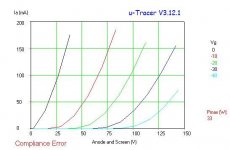
Other thing, is notable the low rp from tubes like PL509. I don't calculated it yet but the "quick test" from µTracer revealed something like 6k. In triode mode this tube eat 6AS7 for breakfast in rp region.
PS.: the measured G2 current is higher for Crazy drive than from G2 only, due to additional resistive current divider. At low anode currents, the G2 sinking current is higher than the resistors drained current
Yes, a considerable less voltage drive for Crazy Drive, but this also confirm the necessity to use a negative supply, unless one can copy the JVC and Super-A idea
(a biasing scheme to "lock" the minimum current in bipolar output transistors, to avoid the resulting minority carrier delay provoked by cut-off). Of course, the "residual" current in PL509 G2-derived drive is too high at Vg2=0V and Vg1=0V with elevated anode voltage (aka the place where the tube must be at cut-off) and will be deleterious to distortion, I presume.Other thing, is notable the low rp from tubes like PL509. I don't calculated it yet but the "quick test" from µTracer revealed something like 6k. In triode mode this tube eat 6AS7 for breakfast in rp region.
PS.: the measured G2 current is higher for Crazy drive than from G2 only, due to additional resistive current divider. At low anode currents, the G2 sinking current is higher than the resistors drained current
Last edited:
Interesting. The configuration I use on the tracer here is a floating power supply in series with the stepped grid voltage from the tracer. I don't have any easy way to tell when I am hitting exactly zero volt sum for the two in series, since there is a continuously variable offset knob on the tracer. So I may be driving the screen grid slightly negative to get the 0 current plate trace (or point below).
6HJ5 has a 5K nominal (datasheet) Rp at 80 mA, and 26LX6 has a 6K nominal Rp at 125 mA. Both working good in Twin drive.
We may not have the divider resistors sufficiently optimised yet to straighten out the plate current or (flatten the) gm curve(s) for the PL509. I think I will order a 40KG6 to try out here. You might try some pots for the divider there to see if it improves further.
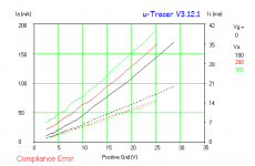
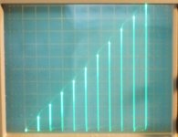
I ran a plate current versus input grid2 voltage step scan (in Twin mode) for 26LX6, shown below. It looks darn close to a straight ramp if you put a ruler up against it. 50 mA/div Vert. and close to 5.4 V steps horiz. I don't have a gm test unfortunately. I tried a 6HJ5 in the same setup and got a nice straight current ramp too. (the ramp shrinks down and curves over if I turn the heater power off to the tube. )
..
6HJ5 has a 5K nominal (datasheet) Rp at 80 mA, and 26LX6 has a 6K nominal Rp at 125 mA. Both working good in Twin drive.
We may not have the divider resistors sufficiently optimised yet to straighten out the plate current or (flatten the) gm curve(s) for the PL509. I think I will order a 40KG6 to try out here. You might try some pots for the divider there to see if it improves further.
I ran a plate current versus input grid2 voltage step scan (in Twin mode) for 26LX6, shown below. It looks darn close to a straight ramp if you put a ruler up against it. 50 mA/div Vert. and close to 5.4 V steps horiz. I don't have a gm test unfortunately. I tried a 6HJ5 in the same setup and got a nice straight current ramp too. (the ramp shrinks down and curves over if I turn the heater power off to the tube. )
..
Attachments
Last edited:
- Status
- This old topic is closed. If you want to reopen this topic, contact a moderator using the "Report Post" button.
- Home
- Amplifiers
- Tubes / Valves
- More Ruminations on Screen Drive/Crazy Drive