Long time lurker, first time poster...
I have some questions about the Triode Dick Single Ended 807 Amplifier design.
It would be helpful if someone could help answer my questions and if they have the time, describe how they derived the answers. I'm trying to learn.
I've built a lot of SS electronics gear but new to building tube amps. I get the basics of electronics but am no expert per say.
Questions as circled in the attached picture:
1. Is the purpose of this switch to allow the filaments to light up and then turn this switch on to apply the B+?
2. What current rating and/or DCR should I seek for the 10H chokes?
3. Power rating and/or PA rating of the OPT if 5K secondary is selected?
4. Any recommendations for an easy to obtain transformer that meet these specs for someone in the USA? Could always add separate filament transformers under the chassis if needed.
Thanks in advance for your time and responses,
Lilstripe
Attachments
Lilstripe,
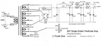
The purpose of the switch in the rectifier filters is to provide a hv standby function. Notice the switch is paralleled with a 180K 2w resistor. This resistor is to provide a leakage path for the electron cloud when the tube is heated ( and the switch in standby) as otherwise there would be no place for it to go and as I understand, such condition is not good for direct heated cathode of the rectifier tube. The two chokes should be rated for at least 150ma each. I would prefer them to be 200ma each but 150s will do. The output transformer should be rated for at least 15 watts so it has some head room against saturation on bass notes. This amplifier will likely make about 9-10 watts output. Output transformers can be purchased for Hammond, Edcor or many others here in the USA. Hope this helps.
Mickeystan
Last edited:
1. Is the purpose of this switch to allow the filaments to light up and then turn this switch on to apply the B+?
Yes. To let filaments to warm up, then KICK DAMNED SPARKS OUT OF THAT POOR TUBES!

Even manufactured as production amps have this STUPID FEATURE, sometimes even controlled by microprocessors!
One other point to consider is the 1st filter cap of 33uf is too large for a 5R4 rectifier. The 5R4 is recommended to only have a 4uf reservoir capacitor. The 5U4 is much better suited as it spec'd at 32uf to 40uf depending upon which data sheet you look at. The CV378 is a tube I do not know anything about so I will not comment on it.
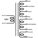
Sorry I missed your 4th question in my original post. Assuming you can do with a 120v primary and do not need a 230v primary, Edcor makes a power transformer that will work for you by simply feeding all heaters except the rectifier tube from one 6.3v winding. You will still want to bias up the filaments with the resistor divider shown connected to the srpp filament winding one the schematic but don't worry it will not cause any problems. The transformer that Edcor makes currently that I am talking about is their XPWR-198. With these specs; 120V, 60Hz. line to 750V (375-0-105-375) at 300mA center tapped with a bias tap at 105V at 25mA, 6.3V at 6A center tapped and 5V at 6A. This transformer is listed with a price of $93.84. The 375-0375 secondary output versus 380-0380v is insignificant.
As for the size of the chokes, I simply swagged them as each should handle 150 ma (half the capability of the power transformer. Further, each channel of this amplifier will likely draw about 50 millamps or a little more at idle and maybe as much as 100ma or so on peaks while playing louder music.
Mickeystan
Further, each channel of this amplifier will likely draw about 50 millamps or a little more at idle and maybe as much as 100ma or so on peaks while playing louder music.
It is SE amp.
Further, each channel of this amplifier will likely draw about 50 millamps or a little more at idle and maybe as much as 100ma or so on peaks while playing louder music.
Waveborn, I must have had a senior moment when I made the above statement. Yes it is a single ended amplifier and I should have said it will draw about 50 milliamps class A in each channel. Thanks for the catch

In this case it isn't so badYes. To let filaments to warm up, then KICK DAMNED SPARKS OUT OF THAT POOR TUBES!
Even manufactured as production amps have this STUPID FEATURE, sometimes even controlled by microprocessors!
The voltage allready goes up with the 18k series resistor and with those chockes no sudden high voltage shock with cathode decoupling C at zero.
Mona
Thanks for the info. Could you go into more detail on how to use this transformer with this schematic. For example, the 5v winding on this transformer doesn't have a center tap but the one in the schematic does. Likewise, how would one use the 6v tap to cover all the filaments and the SRPP setup?
Thanks
Pic attached
Thanks
Pic attached
Attachments
lilstripe,
The 5 volt winding would connect to pins 2 and 8 of a 5U4 rectifier tube (assuming you go with this tube), and then the connection to the standby switch would connect to either pin 2 or 8, your choice it does not matter. You do this as the rectifier filament winding with this transformer does not have a center tap, which is OK. The one 6.3 volt filament winding will serve all tubes for both channels assuming you build two channels to make a stereo implementation. When doing this you will not ground the center tap of the 6.3 volt winding. Rather you will need to connect it to junction of the 390k, 82k and 100uf capacitor (components that used to connect to the center tap of the 6SN7 srpp heaters). The opposite end of the 390k will connect to the place it currently connects to. These two resistors and the bypass capacitor (100uf cap) serve to elevate the heaters to about +75 volts. Having all heaters elevated will not be a problem. Elevating the heaters will help to further reduce any heater induced hum that may come in near the front end of the amplifier. Hope this helps.
Mickeystan
Last edited:
Long time lurker, first time poster...
I have some questions about the Triode Dick Single Ended 807 Amplifier design.
It would be helpful if someone could help answer my questions and if they have the time, describe how they derived the answers. I'm trying to learn.
I've built a lot of SS electronics gear but new to building tube amps. I get the basics of electronics but am no expert per say.
The first thing you need to consider is that hollow state uses DC rail voltages much higher than most solid state. Do be careful.
Questions as circled in the attached picture:
1. Is the purpose of this switch to allow the filaments to light up and then turn this switch on to apply the B+?
This is a real bad idea. Hollow state diodes don't like hot switching and may protest by arcing over. Even if that doesn't happen, they won't last long. Secondly, open that switch and you're 450V above DC ground. That's a nasty shock hazard.
2. What current rating and/or DCR should I seek for the 10H chokes?
The DCR of any decent ripple filter choke should be irrelevant when compared to the total load resistance. Since this is a SE design, the plate current should be ~50mA. That would be the current rating. You have to remember that the definition of inductance:
L= (N * phi)/I
only applies to air coils where the relationship between magnetic flux and current is linear. Ferromagnetics make for a non-linear relationship, but the concept is just so useful that inconvenience is ignored. The current "rating" of the choke has nothing to do with the max current capability of the wire, but rather the current needed to produce the nameplate inductance.
Try measuring the inductance with an RLC bridge, and you're likely to see an inductance of hundreds of henries. Try plugging it into a wall socket while measuring the current, and you're likely to calculate an inductance of a few hundred millihenries.
In the first case, your RLC bridge was using a sense voltage of 1.0VP. Plugging it into a wall socket is likely to saturate the core which greatly reduces the inductance (see above formula and ask what happens if phi can't increase, but current can.)
3. Power rating and/or PA rating of the OPT if 5K secondary is selected?
4. Any recommendations for an easy to obtain transformer that meet these specs for someone in the USA? Could always add separate filament transformers under the chassis if needed.
10 - 15W should be good to go. No need for overkill. Try Edcor

lilstripe,
Ketje (Mona) has the schematic illustrated correctly. In response to my original choke recommendation of 150ma, others have commented that you can do OK with a 50 ma chokes. In my opinion you pushing the minimum limit at 50ma. I originally stated what I did as the Power transformer is rated for 300 milliamps of output current on the original schematic. Please understand that the power transformer has way more current capability than this amplifier needs. Thus it is over kill from the high voltage winding capability. Since this Class A amplifier will draw approx. 50 milliamps if built only a single channel mono or approx. 100 ma if built stereo you can save money on the power transformer as well if you want to built it as needed vs over designed as was originally done by Triode Dick. If you choose to built it with a more appropriate power transformer, I would direct you to use the Allied Electronics transformer part number 70008996 which is their model 6K7VG. This transformer has same set up for the filaments but is built with a 375-0375 volt secondary rated at 150 millamps. Thus, if you want to built this amplifier with this option, the power transformer is available and for sale at Allied Electronics for $52.86. Hope all of this is not leading to further confusion for you. Best of luck on you upcoming build!
Mickeystan
Question - Transformer Related
Hoping to build this design with a laydown style mount transformer (old dynaco st70 style look). I found a decent one commonly available from ClassicTone but the specs are slightly less on the B+. The 6v and 5v are the same.
It would be 710v @ 200ma vs the original design of 760v @ 300ma (which the 300ma looks overkill based on all your previous comments). Would the 710v work or what would be the implications?
How would that play out in this circuit?
Thanks
Lilstripe
- Status
- This old topic is closed. If you want to reopen this topic, contact a moderator using the "Report Post" button.
- Home
- Amplifiers
- Tubes / Valves
- SE807 Triode Dick Amplifier Questions