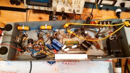
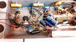
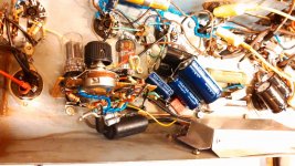
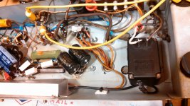
Isn't that a B+ cap right below the tone controls? If it is an "early stage" B+ filter, that's big buzz voltage a few cm away from your sensitive tone network.
Yeah, I know. The caps will have to be moved if this TS shield doesn't work. The caps are mounted to the socket pins of a former "canister" style cap that housed two or three smaller value caps. The canister was mounted using an octal socket base.
Thanks again everyone.
What does it mean if the amp squeals after the 5U4G rectifier has been replaced with two diodes and a high-watt resistor in a full-wave arrangement? This is what I did - in order to learn - with the understanding that SS rectifiers can handle larger amounts of capacitance value for C1. The tone controls modulated the frequency of a ~3.5kHz signal to some degree, and controlled the amplitude in a big way. While I did not change the value of C1 (40uF to suit the tube rect), I added 100uF to the screen filter (C2 or C3, I'm away from the bench in writing this) and the noise went away. The 100uF did almost nothing to change the amount of ripple on the output. (by how much did it change the ripple on the screen? I'll post that later)
I did calculations for the amount of ripple that should be expected on C1, with the formula:
I(185mA) / [2f (120Hz) * F (.00004)] = Ripple in mV
The answer was 38.5volts, RMS. If the amp has this much ripple on the plate supply, and 40+mV are found on the output, which part of the output stage is responsible for the failure to cancel out the remaining hum?
1. Power tube mismatch? (in the amount of current that they each draw?)
2. OT primary winding resistance? (winding inductance properties are the main interest, but would a 10 ohm difference between the sides mean anything?)
3. Screen grid waveform/voltage values? (for some reason, tube A has a fuzzy, rect. sine wave shape (fuzzy half waves), while tube B has a perfect sawtooth profile)
Aardvarkash10, the SL7 uses much less current and has a mu of 70, that looks very appealing! How will it mess up the bax TS?
The 6SL7 Achieves that high-u by driving up the rp. The source impedance is part of the resistances of the TS, and driving up that source resistance will drastically shift the poles 'n' zeros of the TS. It won't perform like you expect.
...The source impedance is part of the resistances of the TS, and driving up that source resistance will drastically shift the poles 'n' zeros of the TS. It won't perform like you expect.
The poles are the "peaks" of the spectrum and the zeros are the low points? When you say poles and zeros, are we talking about how flat the frequency response will/can be? Otherwise, I understand why the source impedance is a factor. When I was building a TS in Duncan's TSC (thank you Duncan!!), I saw the effect of placing different values into the stack, but I might better understand the implications if there were voltage and current measurements across the tonestack as a whole. The point would be to understand the expected losses across the tonestack with a particular source (with values V,I, and Z).
Randall Aiken's website (Aiken Amps) had a post in the white paper section about the "scaling" of impedance's. Having just read this yesterday, I realized that the values in the Rock'ola project TS were chosen through trial and error, and who knows what the net Z was for a given frequency. It (Z) could be calculated, but it seems that by consciously "scaling" the values up or down in harmony, there would be some benefit, including the reduction in one's investment of time.
Tell me if this is ridiculous, I chose bass/treble ratio components with higher values of Z, as it seemed to move the net spectrum further upwards, in the direction of less loss. It also seemed that if the TS consumed less current, that there would be a larger amount left to enter the following stage.
Update #2, regarding Power Amp statistics
New tests, with the 100uF cap added to screen supply, and 4x n4007 diodes (arranged with 2 diodes in series for 2000V protection) in a Full wave formation, followed by a 5W 47R MO resistor replacing the 5U4G.
Reason for the upgrade: Possibility of reducing output ripple hum with larger stores of C1-C3 capacitance, benefit from higher circuit B+ (marginal, 20-35 volts), lower PT core saturation (5V heaters unused at the moment), less wasted power from supply-side resistance (5U4G). Learn.
458V on C1
-26.4V across cathode, 124mA* draw from a pair of 5881/6L6 (designed for 6L6, using 5881 for testing)
Power tube A:
453.5V on plate
92.6R across plate/B+
4.6V drop across winding = 49.6mA *
*there is a discrepancy in the tube current results
Screen .73V drop across 410R,
1.8mA = 1.3mW at idle
~~~signal, 120Hz, 22mVpp
Grid 120Hz, 80-90mVpp w/ sharp peaky tops to waveform
Power tube B:
452V on plate
101.5R plate/B+
5.6V drop = *55mA
*there is a discrepancy in the tube current results
Screen 1.1V drop across 410R
2.7mA = 3mW at idle
~~~signal, 120Hz, 40mVpp
Grid 120Hz, 30-40mVpp w/ "squarish" rocky tops to waveform
PICTURES AND LAYOUT
Changing the value of C1 to 60uF (+20uF) made~no difference in output hum.
Changing Tube B to another tube eliminated 80% of the differences between signal levels on the screen and grid. Both tubes (now) have lower levels of grid input ripple.
Output ripple is magnified with use of the bass control (input signal related). What can be done to shield the 8" of B+ conductor bringing the audio signal from 6J5 to plate resistor to TS (long yellow wire from top left of amp, underneath "card" and to shielded TS)? The plate resistor is right underneath a bunch of filter caps, as is the coupling cap leading to the TS. The shield is not fully mounted, but is grounded.
Attachments
More pictures and questions about layout. I won't be hurt by comments about how "back alley" this looks, it's my first expression of audio engineering and I'm damned proud of all that it takes to get this far.
So far, it looks like there's something to be learned about the placement of filter capacitors. In reading, it sounds like a good idea to place a filter capacitor nearest the stage it is filtering. To expand on this topic, the placement of filter capacitors must also depend on how much ripple current is remaining on their supply when it leaves the capacitor. Is this solid theory so far? If so, I will likely be moving all of the filter capacitors in the middle of the amp, nearest the TS, power tubes and DIY card, to the right hand side where C1 sits. I will also order some larger value caps so that they aren't "double-stacked" everywhere. Would some like to comment on this idea? My customer wants the amp now... I want it done right.
More to say about this amp - The music sounds "distant" in the midrange. NFB clears this up a good bit, but nothing extraordinary. There is a beautiful "air" to the sound, very rich and potentially pleasing, but the hum and noise are expensive attention robbers. Noise is the rushing "hush" and "hiss" of non-musical sounds. It feels like the noise is "half" as loud as the music (no Log jokes please), when auditioning quieter songs like David Gilmour's On an Island album.
- Status
- This old topic is closed. If you want to reopen this topic, contact a moderator using the "Report Post" button.
- Home
- Amplifiers
- Tubes / Valves
- Reaching max Rect. Current and amp needs more gain.


