Hi guys,
I think this is kind of a newbie question. but... What output transformer spice model do you usually use in your simulations?
I'm using the XFRM_NONLINEAR from the breakout lib, but I this model doesn't include the dc impedance and I think doesn't properly model the reactance either.
thanks for the attention
-Miguel
Hi
what spice software are you using?( I use Mcap 7)
I usually model output trafo with coupled chokes.
If I also had to simulate hysteresis than I
chose an appropriate non linear core.
DC resistance, parassitic capacitance and
leakage inductance are non difficult to add.
Federico
what spice software are you using?( I use Mcap 7)
I usually model output trafo with coupled chokes.
If I also had to simulate hysteresis than I
chose an appropriate non linear core.
DC resistance, parassitic capacitance and
leakage inductance are non difficult to add.
Federico
and in a paper Marshall Leach wrote in the Journal of the Audio Engineering Society --(Vol 43 No. 3, 1995 March pp 117-126)
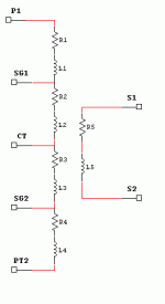
*Transformer Model Subcircuit
.subckt trans p1 st1 ct st2 p2 s1 s2
R1 P1 1 "R1"
L1 1 SG1 "L1"
R2 SG1 2 "R2"
L2 2 CT "L2"
R3 CT 3 "R3"
L3 3 SG2 "L3"
R4 SG2 4 "R4"
L4 4 P2 "L4"
R5 S1 5 "R5"
L5 5 S2 "L5"
KALL L1 L2 L3 L4 L5 "k"
.ends
Leached used 0.9988 as the coupling constant KALL
*Transformer Model Subcircuit
.subckt trans p1 st1 ct st2 p2 s1 s2
R1 P1 1 "R1"
L1 1 SG1 "L1"
R2 SG1 2 "R2"
L2 2 CT "L2"
R3 CT 3 "R3"
L3 3 SG2 "L3"
R4 SG2 4 "R4"
L4 4 P2 "L4"
R5 S1 5 "R5"
L5 5 S2 "L5"
KALL L1 L2 L3 L4 L5 "k"
.ends
Leached used 0.9988 as the coupling constant KALL
Attachments
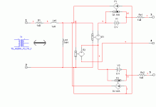
Here's the SPICE model for "AUdio Transformer 10:1
in Multisim:
.SUBCKT ts_audio_10_to_1 1 2 3 4 5
* EWB Version 4 - Transformer Model
* n= 10 Le= 1e-006 Lm= 0.001 Rp= 1e-006 Rs= 1e-006
Rp 1 6 1e-006ohm
Rs1 10 3 1e-006ohm
Rs2 11 5 5e-007ohm
Le 6 7 1e-006H
Lm 7 2 0.001H
E1 9 8 7 2 0.05
E2 8 4 7 2 0.05
V1 9 10 DC 0V
V2 8 11 DC 0V
F1 7 2 V1 0.1
F2 7 2 V2 0.1
.ENDS
You can adjust the values for 100:1 etc. I attach also a sketch of what the SPICE connections seem to be (node 12 on the schematic is node 7 in the sub-circuit model)
Attachments
That model is backwards
The center tap should be on the primary and this will not work by just reversing pri for sec like a real transformer.
I'm going to take a crack at this because I have an entire Fender Deluxe Reverb-AMPAB763 modeled in Micro Cap with the exception of the O/P transformer.
Why is this so difficult to find?
The SPICE code and the pic really helped though. I should be able to go the other way with it.
Thanks!

and in a paper Marshall Leach wrote in the Journal of the Audio Engineering Society --(Vol 43 No. 3, 1995 March pp 117-126)
Leached used 0.9988 as the coupling constant KALL
couplingfactor "k" 0.9988 seems a bit low and even with high impedance pentode drive would give only mediocre high frequency response.
I assumed this transformer had much tighter coupling.
Are you sure "k" is not 0.99988 instead?
- Status
- This old topic is closed. If you want to reopen this topic, contact a moderator using the "Report Post" button.
- Home
- Amplifiers
- Tubes / Valves
- output transformer spice model