Guys
Years ago i bumbled my way around anf FVP linestage. It did not work. It was sent to JoeR and he rescued it. It sounded great. I hardly used it though as life as a 20 year old can change so much.
In the last 12 months i moved from Sydney to a regional town and was blessed with a 5 car garage. So i started to get back into audio.
So the orivional FVP has been removed from service
I have now built a varient of the FVP and SVP with phono stages.
I varied it quite a bit using kandkaudio shunt reg and ccs. I have one per channel.
The SVP sounded a little better than the FVP. With either super reg or the kandk reg.
I ended up using 6922s in phono and 5687 in line. However i have found the 5687s that i have to be very microphonic and very very hot. I am about to try and make the linestage with 6922.
Apart from that i would like to talk to people who have made the phono stage. At the moment i am not happy with it. Relative to the linestage the phono is a little harsh and condensed sound stage. I am not sure i have it setup right. And the riaa has not been trimmed or tested. That is something i want to work on.
I also wish to just try other things and play with this circuit. I have buckets of 5842s, 5687 and 5670 even 5965. All bought 20 odd years ago. I even bought a couple of ec8010 to have a fiddle with. I might even look at an all tube MM phono.
I am also using a khozmo 50k attenuator but not sure if suitable. I do not know if it maintains a constant 50k across the range.
I would love some advice or shared experience on builds. I have read other guys posts and blogs mainly about the linestage but looking for more.
Anthony
5687 can be microphonic but experience has shown me that this is an instability issue rather than real microphonics. Adding grid stoppers and elevating the heaters usually tames the instability. However since this is a stacked arrangment you will need to be clever about how you use your 5687 elements to ensure that the upper voltage follower is elevated above its cathode. The best solution would be to use one bulb to do voltage follower duty for both channels.
Get the 5687 right and it will sound far fuller and more natural than any 6922, and will have less gain to waste as well (excessive gain is the bain of the FVP design).
Shoog
Get the 5687 right and it will sound far fuller and more natural than any 6922, and will have less gain to waste as well (excessive gain is the bain of the FVP design).
Shoog
Shoog
As per Allen SVP schematic I have the heaters on the 2 upper triodes to 150V and the input tube and bottom tube raised to 50V. (Allen says 30V though) i use a voltage divider string on one reg to get all 3 required voltages.
I was getting about 60V out of the FVP. The SVP can put out about 35V. (Around 1 volt input, but i can test that again)
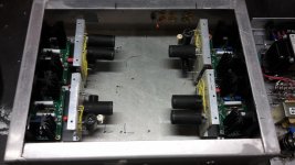
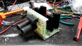
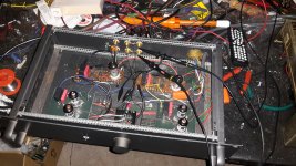
I know in the current incarnation that i am using. The brown rack mount unit. The HT has a fair amount of hash on it. This is also true of the super reg version. The FVP with super reg the ccs was in a seperate case. Then an umbilical to the shunt reg. Then it was split off to the line modules. However with the SVP i have the kandk ccs and reg in a seperate chassis. Umbilical to the linestages and phono. I do not have any stability type networks on it. Maybe a couple of diodes and a cap from Ht ground to earth at the distribution point?
Also i have noticed the the very cheap cd player that i have injects noise while it is turned on. Plus the fluro lights i have also inject noise. It does sound better with the lights off.
With the next incarnation of it. I have mounted the ccs and shunt regs about 1.5 inches away from each stage module. I had been reading the salas shunt reg thread which these are based on. I did not get all they way. But i did get to some pages that suggested the
Shunt reg should be close to its usage point. I think b i got about 120 pages in.
This next version is dual mono power supply then each s tage has itts own ccs and shunt reg.
Anthony
As per Allen SVP schematic I have the heaters on the 2 upper triodes to 150V and the input tube and bottom tube raised to 50V. (Allen says 30V though) i use a voltage divider string on one reg to get all 3 required voltages.
I was getting about 60V out of the FVP. The SVP can put out about 35V. (Around 1 volt input, but i can test that again)
I know in the current incarnation that i am using. The brown rack mount unit. The HT has a fair amount of hash on it. This is also true of the super reg version. The FVP with super reg the ccs was in a seperate case. Then an umbilical to the shunt reg. Then it was split off to the line modules. However with the SVP i have the kandk ccs and reg in a seperate chassis. Umbilical to the linestages and phono. I do not have any stability type networks on it. Maybe a couple of diodes and a cap from Ht ground to earth at the distribution point?
Also i have noticed the the very cheap cd player that i have injects noise while it is turned on. Plus the fluro lights i have also inject noise. It does sound better with the lights off.
With the next incarnation of it. I have mounted the ccs and shunt regs about 1.5 inches away from each stage module. I had been reading the salas shunt reg thread which these are based on. I did not get all they way. But i did get to some pages that suggested the
Shunt reg should be close to its usage point. I think b i got about 120 pages in.
This next version is dual mono power supply then each s tage has itts own ccs and shunt reg.
Anthony
Shoog
As per Allen SVP schematic I have the heaters on the 2 upper triodes to 150V and the input tube and bottom tube raised to 50V. (Allen says 30V though) i use a voltage divider string on one reg to get all 3 required voltages.
I was getting about 60V out of the FVP. The SVP can put out about 35V. (Around 1 volt input, but i can test that again)
I know in the current incarnation that i am using. The brown rack mount unit. The HT has a fair amount of hash on it. This is also true of the super reg version. The FVP with super reg the ccs was in a seperate case. Then an umbilical to the shunt reg. Then it was split off to the line modules. However with the SVP i have the kandk ccs and reg in a seperate chassis. Umbilical to the linestages and phono. I do not have any stability type networks on it. Maybe a couple of diodes and a cap from Ht ground to earth at the distribution point?
Also i have noticed the the very cheap cd player that i have injects noise while it is turned on. Plus the fluro lights i have also inject noise. It does sound better with the lights off.
With the next incarnation of it. I have mounted the ccs and shunt regs about 1.5 inches away from each stage module. I had been reading the salas shunt reg thread which these are based on. I did not get all they way. But i did get to some pages that suggested the
Shunt reg should be close to its usage point. I think b i got about 120 pages in.
This next version is dual mono power supply then each s tage has itts own ccs and shunt reg.
Anthony
What you describe is very much like parasitic's modulating into the signal. external light sources should have no impact on your signal. Long signal wires between your power supply and SLCF stages sound like the likely culprit. Your solution sounds promising.
Shoog
I built the FVP5A a few years ago and still use it as my pre-amp. The power supply is dead simple with no regulation just a lot of cascaded LC and RC filters. I have Russian 6N6P's in the gainstage. Specs are similar to 5687, ECC99 ie lower mu and higher gm than the 6922. Cheap and pin-compatible with the 6922 so no socket re-wiring compared with the 5687's. I know, I'm lazy!
With the phono section I used precision resistors and either good industrial type caps or Russian ex-military caps. I haven't trimmed or tested the phono stage as I don't have the equipment. I don't listen to a lot of vinyl but to me it sounds real close to the line-stage. Allen strove for a clean, clear sound - a lot different to the warm, smooth sound some may expect from vinyl. I know it surprised me how similar vinyl sounds compared to my (modified) CD player.
Regarding the attenuator, can't you just measure the resistance over its range?
Rod
OK. So i have gotten one channel up and going.
Initial tests look good. HT is quieter than last version.
Unfortunately for me my mate insists on MC of 0.3mV.
At the moment the phono stage has 55db and the line stage (5687) has 13db.
I was shooting for 65 and 20. But i realise now that that 20 for the 5687 linestage may be unreachable.
In the phono. I am running 15ohms on the jfet and 392 on second tube. I was initially on 22ohms but 53db.
My HT is 270 my plate resistors are 27K. I do however get 120 on the forst plat and 100 on the second. In the linestage i get 120 on the plate and 120 on the hotside of the output cap.
Any suggestions?
Anthony
So decided to run some audio through the channel.
Linestage sounded great. I little better than the last. I would think because of quieter power supply location.
The phono however was bloomy if that is a word and low in volume. However i am testing a MC setup srage with a MM.
I went back to some measurements and found the oveall gain dropped to 45db. Dissconnect amplifier and it goes back to about 68db.
I also noticed subsonic fluctuations on the powersupply and on the signal. Its not a sine wave just minor changing valus around the 1hz bur varies. I can watch my speakers move in and out according to my scope. I did have this before on previous version but it went away for no explained reason.
Anthony
I now have the overall gain up to 75db. Hopefully that will be enough.
I have one other issue. When in phono stage a get some sort of random low frequency instability. If i turn it up to full volume i can get about 100mv of verylow frequency events. They go up and down with volume. They do not occur in the linestage by itself. The first place i notice it is the first plate on phono. I have 100 ohm grid stoppers.
Anthony
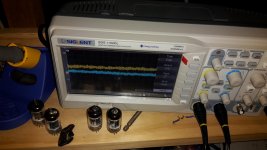
Lights on and lights off
I have some florescent lamps in the den that cause similar interference in my amps.
The ballast in lamps are now electronic instead of magnetic as they were years ago.
I suspect LED lamps may potentially cause similar problems.
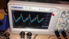
So this is what i am getting.
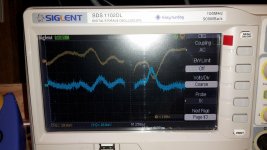
The yellow trace is the entire output of the pre. The blue trace is the output of the phono. This is with a shorted input. The first place this appears is on the plate of the grounded grid. The second pic is with volume turned down.
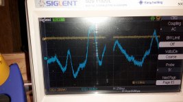
I have everything in the garage disconnected, except scope and pre. The hash is external noise at about 1mV. But it is noise picked up by scope. I know the low frequency stuff is real. Because i can see my speakers move.
The yellow trace is the entire output of the pre. The blue trace is the output of the phono. This is with a shorted input. The first place this appears is on the plate of the grounded grid. The second pic is with volume turned down.
I have everything in the garage disconnected, except scope and pre. The hash is external noise at about 1mV. But it is noise picked up by scope. I know the low frequency stuff is real. Because i can see my speakers move.
Attachments
Shoog
No not yet. Are you suggesting ringht on the input of the phono. Or introduce it on the same node as the first part of the RIAA. Or put in on the input of the linestage?
Just been trying to learn about them for now. I was about to go back and read cookbook, but i do not recall anything like that in there. However i do tend to read with a thought in mind.
Anthony
So this is what i am getting.
The yellow trace is the entire output of the pre. The blue trace is the output of the phono. This is with a shorted input. The first place this appears is on the plate of the grounded grid. The second pic is with volume turned down.
I have everything in the garage disconnected, except scope and pre. The hash is external noise at about 1mV. But it is noise picked up by scope. I know the low frequency stuff is real. Because i can see my speakers move.
Just some thoughts that may lead to a better undertanding about your noise situation:
Can you confirm what equipment you have connected for those tests. Is there also an amp with speakers?
Can the cro be battery powered? That would provide a non-mains connected reference measurement. Other forms of measurement are problematic, as an AC voltage or coupled measurement would need to go down to very low frequency.
This is a mains related measurement, but do you have any voltage signal between protective earth and neutral?
If you divided down the B+ supply and probed that, with normal grounded input preamp loading, and when the amp loading is replaced with a similar powered resistive load, do you see a similar low frequency signal?
Ciao, Tim
Since the signal is been coupled into your preamp from an external mains source, its getting there in a number of ways, it could be polluting the earth plane, or it could be coupling into the preamp via its cathode, grid or plate. Stoppers on the grid and the plate would eliminate these as the cause. A stopper can be as simple as an appropriately sized resistor which combined with the input capacitance creates a high pass filter.
Systematically trying each node with a stopper until the signal is damped. If its the ground coupling the signal then you have to think hard about your grounding philosophy.
I have found that single point star grounding has never failed to deliver a silent build no matter how otherwise messy the build is.
Shoog
Thanks for the help guys
I will give the methods a go. Being blessed with 2 young children i may have to just try the stoppers first. Maybe 10ohms on the plate? I do have a little length on the mills mra that could be an issue. I have always been a little uneasy about the 25u 25v cap on the voltage divider on the grid for the grounded grid. This is just gut feel not based on any expertise that i have very little of.
I was reading Patrick Turners webpage. Of which i am only capable of absorbing little piece at a time. I was reading about the LC input choke and the CLC filters on the power supply. There he alludes to subsonic noise. But i think he is referring to sinusoidal.
I tend to only find time to read and not do with young children that seem drawn to electricity, but i feel may be strangely alergic.
Anthony
Ok so tonight i tried a couple of things.
Shoog
I put plate stoppers of 8.2 ohms on both sections of phono stage. No real change except for more hash. 8.2 was nearest i had for 10 ohms. Which capacitance am i looking at here. I ran a hight pass formula with whatever 1.4uuf is plat to grid and 8.2 ohn resistor and hot megaHz.
Throbins
my scope is AC power input only.
I did try scoping my mains between neutral and safety ground. And i got what appeared to be 240ac. I then went hey lets try active and ground and i got about 2.5 volts peak to peak. Then i was confused and turned everything off.
The dude that owned the house before us was an electrician and i have found more than one item of concern. Garage may be wired wrong. I am about to check other items. But my wiring on iec mains connector with switch and fuse built in look correct.
So i just found out that a powerboard that has been in our family since i was a child. Maybe even before was wired incorrectly. This was a hand made powerboard. I have since destroyed it and thrown it out. Still has bakelite sockets.
Having said that. It did not resolve my issue.
Throbin. So when i did get a chance to measure the mains between neutral and safety groung. I got like a nipple waveform of about 1.5 volts p/p that appeared to have a heart beat. As in it seemed to change size about every second
Having said that. It did not resolve my issue.
Throbin. So when i did get a chance to measure the mains between neutral and safety groung. I got like a nipple waveform of about 1.5 volts p/p that appeared to have a heart beat. As in it seemed to change size about every second
There is risk in any mains side measurement - for the possible situation you found yourself in! Forums are caveat emptor, and sometimes ban any mains side discussion for a very good reason. Anyway, I'm pleased you have identified a bad case of diy mains wiring, and didn't damage yourself or your test equipment.
Normally, a small neutral-PE voltage is common, and typically indicates neutral wiring impedance and current flow between the point of measurement and the nearest PE-neutral bar link (eg. your main distribution board). If your abode had substantial or noisy neutral current, and/or high neutral path impedance, then that may affect audio equipment you are using - either as additional noise voltage coming through the mains and passing in to the DC side circuitry, or em coupling in to sensitive nearby wiring/cables equipment. Such a noise issue is within your abode, and not per se caused by the electric utility quality of supply. If that neutral earth voltage waveform had characteristics time-aligned or similar to your audio noise issue, then that would further your investigation.
Normally, a small neutral-PE voltage is common, and typically indicates neutral wiring impedance and current flow between the point of measurement and the nearest PE-neutral bar link (eg. your main distribution board). If your abode had substantial or noisy neutral current, and/or high neutral path impedance, then that may affect audio equipment you are using - either as additional noise voltage coming through the mains and passing in to the DC side circuitry, or em coupling in to sensitive nearby wiring/cables equipment. Such a noise issue is within your abode, and not per se caused by the electric utility quality of supply. If that neutral earth voltage waveform had characteristics time-aligned or similar to your audio noise issue, then that would further your investigation.
Last edited:
- Home
- Amplifiers
- Tubes / Valves
- SVP and FVP preamp builders