Hi Everyone, I think I just found my next project...
Anyone notice Pete Millett's newest tube projects? I was headed over to check out the new Engineer's amplifier mono blocks and there are two new projects posted. I ain't stumping here for Pete (I have one of his compaction triple triode driver boards) and to be honest, I am behind in my projects a bit, but these are damn interesting.
NuHybrid Headphone Amp
Nutube 6P1 Buffer PCB
I know that George and Pete (and Nelson Pass over in the sandier parts of diyaudio) are among the best designers and experimenters here, but I think Pete has upped his game in my book with this new "tube". I totally get it, but never in my diy life would have ever thought that something akin to my Commodore C112 would ever be used for something like these projects. And the price and voltage is just right.
Right now, the headphone amp looks like the one to build for me because it is going to be hard to knock out the Pass B1 Buffer I got going (at least for the time being...).
* my 12 year-old son has gotten a mild case of the electronics bug between wanting to take apart my typewriters, that one particular C112 desktop calculator, and silverface SS amplifiers, he wants to build something "sick" looking and the headphone amp might just be the thing.
I read through the design and schematic too and it is a really interesting looking amp. The NuTube is quite a funky little part and I'm sure Pete squeezed maximum performance out of it.
From the data sheet: direct heated @ 0.7V, 1.7mW max dissipation, only class A2 really practical, 14.5 Mu, 250k Rp, 54 uA/v transconductance
From the data sheet: direct heated @ 0.7V, 1.7mW max dissipation, only class A2 really practical, 14.5 Mu, 250k Rp, 54 uA/v transconductance
I saw the initial press release about a year ago and signed up for advanced mailings and technical data. I knew that the NuTube is just a modified VFD display, and remembered my experiments 20 or 25 years ago with the VFD ripped from a wrecked 1985 Dodge that I parted out. I ripped up the car to get the turbo engine and transmission since I was racing turbo Dodges at the time. I grabbed the dash thinking I could make the digital stuff work in my older smaller 2 door Omni, but it didn't physically fit. I figured out that the VFD is basically a specialized DHT with fluorescent material on the plate, so I wired one up and connected my guitar to it. It amplified, distorted in a pleasing manner, but couldn't do a clean tone very well. I had a small matter of designing a wiring harness to fit a 1985 digital fuel injected engine into a 1982 carbureted car, so I forgot all about the VFD.
More recently I got a pair of VFD clock modules for $4 surplus. I wired one of them up as a triode amp and it will take some more tweaking, but the results are similar. Very low plate current, microamps. Lowish gain with less than great linearity. I haven't fully explored operation beyond 12 volts though.
At $50 each, I don't see any NuTube tinkering in my near future since I have no immediate need for such tech.....I have a box full of 40's and 50's vintage hearing aid tubes to tinker with. Some of them can be found relatively cheap, and some work with 22 volts on the plate. See the 6418 datasheet.
Here are links to other NuTube threads:
http://www.diyaudio.com/forums/instruments-amps/304392-one-hundred-fifty-watts-korgs-new-triode.html
http://www.diyaudio.com/forums/tubes-valves/268852-new-tube-tech-korg.html?highlight=korg+nutube
http://www.diyaudio.com/forums/vend...w-available-online.html?highlight=korg+nutube
Attachments
I can still get the 12K5 NOS NIB for $3 so I won't be trying the new korg tube any time soon either.
https://frank.pocnet.net/sheets/127/1/12K5.pdf
https://frank.pocnet.net/sheets/127/1/12K5.pdf
George, if the displays you have are clock displays, then maybe a PSE build using the whole of the VFD digits/display (and not just a single digit) might even things out linearly (but you probably pondered that over breakfast a few years ago ).
Other than newer manufacturing practices and tighter controls, I wonder how they got this NuTube to act nicer. And if this is a triode, they why add the phosphor to make it a VFD and not just a plain old triode?
Either way, it probably is an upgrade to my CMoyBB which I am now noticing my son has sitting between to my "cans" and his desktop (I love my son, but he better hang those headphones back up proper).
).Other than newer manufacturing practices and tighter controls, I wonder how they got this NuTube to act nicer. And if this is a triode, they why add the phosphor to make it a VFD and not just a plain old triode?
Either way, it probably is an upgrade to my CMoyBB which I am now noticing my son has sitting between to my "cans" and his desktop (I love my son, but he better hang those headphones back up proper).
I felt the same way about tinkering and the high cost. I have plans to make a VFD based hybrid but I plan on using a pair of IV-15 or DM160 indicating triodes for that.
Don't get me wrong, I've fantasized about a NuTube portable hybrid since I heard them coming out but can't bring myself to pay $50 when I have a box full of miniature and subminiature battery tubes at home.
Don't get me wrong, I've fantasized about a NuTube portable hybrid since I heard them coming out but can't bring myself to pay $50 when I have a box full of miniature and subminiature battery tubes at home.
At $50 each, I don't see any NuTube tinkering in my near future since I have no immediate need for such tech.....I have a box full of 40's and 50's vintage hearing aid tubes to tinker with. Some of them can be found relatively cheap, and some work with 22 volts on the plate. See the 6418 datasheet.
That is my feeling as well. I have a couple hundred 6418, and they can sound very nice. Unfortunately, also rather microphonic.
Unfortunately, also rather microphonic.
I have not met a "battery tube" that isn't microphonic. All are directly heated, and some have thinner filament wires than others. The thinner the wires, the more they vibrate.
I'm thinking of using six of them for a guitar preamp, one for each string using piezoelectric bridge string saddles (ghost pickup). The microphonics may help the sound, or make it worse. The only way to find out is to build it.
PSE build using the whole of the VFD digits/display (and not just a single digit) might even things out linearly
My experiments with the cheap clock display have been done with all (or most of them, I might have missed a few) plates wired in parallel. I only played with it for an hour or so before losing interest.
And if this is a triode, they why add the phosphor to make it a VFD and not just a plain old triode?
The "plate" in a typical small VFD is segmented. There are several "plates," one for each segment in the display. In a small VFD the grid is one piece that goes between the filament wires and the array of plates. A positive voltage is applied to the grid to attract electrons from the undersized filaments and toward the plates. Each plate is controlled, zero or a negative voltage turns the segment off, and a positive voltage turns it on. Sometimes the grid voltage can be varied (or pulse width modulated) to control the brightness of the entire display.
The grid voltage to plate current relationship has no meaning to the use of the VFD, so it's not even a parameter that is tested during the design or manufacture of a VFD. Display brightness is the major design factor.
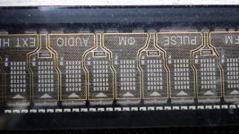
The Korg NuTube has one large plate for each triode, with a grid structure optimized for some degree of linearity. The plate could be coated, which may or may not affect linearity, or at least a cool logo graphic could be printed over a small area. The photo posted on the early release data that I have shows a small phosphor patch in the center of each plate structure. No idea if this made it to production. There is only a single filament wire running across the entire "tube" tapped in the center to allow separate operation of each triode. The filament is rated for 0.7 volts and 17 mA. Clearly not a huge amount of electron emission. The clock I have has 3 filament wires, and the HP display has 6.
Larger VFD's have a segmented grid structure in addition to the plate. This allows for multiplexing of complex displays. Both grid and plate must be positive for a segment to light up.
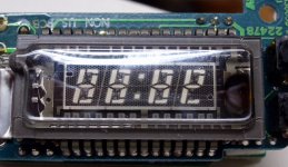
Enclosed are two pictures. The first is the $2 surplus clock that I have. The grid is ole piece of perforated metal. The second is a piece of a large Hewlett Packard VFD in a $20K RF signal generator. You can see that each digit of the display has a separate grid, and each tiny segment of each digit is a separate plate. There are several TI SN75518 VFD display driver chips on the board to handle the display multiplexing.
There is a paper on Noritake's web site giving some basic information on how the VFD's operate and how they are electrically connected. No info about linear operation though.
https://www.noritake-elec.com/technology/general-technical-information/vfd-operation
Picture:
http://korgnutube.com/en/
Attachments
Last edited:
- Status
- This old topic is closed. If you want to reopen this topic, contact a moderator using the "Report Post" button.
- Home
- Amplifiers
- Tubes / Valves
- Pete Millett's new VFD based headphone amp and buffer