Hello all,
I'm wondering if there is any significant problem using the typical fixed bias grounded cathode differential pair that is so commonly seen as a power amp circuit, but in a preamp circuit, in this case as a driver. This would not be a phase inverter- it would follow a phase inverter.
I'm aware of the basic issue with providing a clean bias supply. I'm wondering why I haven't yet seen this version of a differential pair anywhere other than a power amp, and yet it's so common as a power amp circuit. No need for a long tail, and the HT taken up by a long tail, and no apparent need for a constant current sink either, as far as I can tell.
Why not? Perhaps I just haven't seen enough schematics.
Thanks!
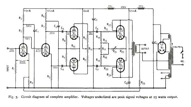
It's not uncommon to see a pair of grounded-cathode stages with a shared bias resistor (a 'short tailed pair' if you like), after a phase inverter. Think Williamson amplifier.I'm wondering why I haven't yet seen this version of a differential pair anywhere other than a power amp,
But we don't normally use fixed bias because it is unecessary; the bias voltage is small (few volts) and you're not trying to maximise output power from the tubes, so cathode bias is fine.
A 'differential pair' with no tail is just a pair of separate grounded-cathode amplifiers which the circuit just happens to use for antiphase signals. This is what most PP output stages are: a pair of separate stages, not a differential pair.
No connection with fixed bias, as bias is largely independent of the tail.
Why does the OP think there might be some advantage in using an inappropriate circuit, just because that circuit is appropriate in a different context?
No connection with fixed bias, as bias is largely independent of the tail.
Why does the OP think there might be some advantage in using an inappropriate circuit, just because that circuit is appropriate in a different context?
That's what I thought must be so- and yet in the typical PP output stage differential input signals and odd order harmonics are summed, and common mode input signals and even order harmonics are cancelled, just like a differential pair. So what does a genuine differential pair offer that "just a pair of separate grounded-cathode amplifiers which the circuit just happens to use for antiphase signals?"
I imagine it's just better at the same job?
I thought since the signal at the cathode junction must be zero with the grounded cathode quasi-differential pair, it might actually do a better job than a genuine differential pair with a tail resistor instead of a constant current sink.
Fixed bias could be a way of better matching the performance of the tube amplifying each phase. I can see that it's typically simpler and adequate to use a cathode resistor or CCS with reasonably well matched valves.
It's not uncommon to see a pair of grounded-cathode stages with a shared bias resistor (a 'short tailed pair' if you like), after a phase inverter. Think Williamson amplifier. <snip>
The kind of driver I'm referring to is not a cable driver but the driver stage for a power amp. Although I'm not concerned with maximizing output power, I am concerned with maximizing output swing, so I'm hesistant to sacrifice HT to a tail resistance. Plus I have a bias supply handy for the the output stage, and just looking at them both, I thought why not?
Still, I can see why it is not a more common approach- nonetheless I can't see any reason why it can't be done- so I thought I'd ask.
Thanks all!
Asymmetry causes DC bias of transformer core. Even if signals are counter-phase and equal by amplitude, when time constants in coupling caps and grid leak resistors are different (think of bias adjustment pots or 20% tolerance of capacitors) resulting phase shifts on low frequencies does the same, modulating core permeability of cores and bias of tubes.
A differential pair can produce a differential output from a single-ended input; it has common-mode rejection. A pair of gain stages fed in antiphase simply output whatever they have been given; no common-mode rejection.So what does a genuine differential pair offer that "just a pair of separate grounded-cathode amplifiers which the circuit just happens to use for antiphase signals?"
A better job at what? Amplifying an existing differential signal? No, no better and no worse than a differential pair. Converting a single-ended input to differential? No, much worse - it can't do this at all; only a proper differential pair with a long tail does this.I thought since the signal at the cathode junction must be zero with the grounded cathode quasi-differential pair, it might actually do a better job than a genuine differential pair with a tail resistor instead of a constant current sink.
A differential pair can produce a differential output from a single-ended input; it has common-mode rejection. A pair of gain stages fed in antiphase simply output whatever they have been given; no common-mode rejection.
QUOTE]
I keep reading about pp output stages rejecting even order harmonics generated in the stage and rejecting hum- perhaps this is not even true of pp output stages without a common cathode resistor?
OUTPUT stages with a transformer cancel in the transformer.
Yep, with cancellation common mode currents in tubes, transformers, filter capacitors...
I keep reading about pp output stages rejecting even order harmonics generated in the stage and rejecting hum- perhaps this is not even true of pp output stages without a common cathode resistor?
It is true, in pauses. When music plays hum adds to music and intermodulates with it.
As they said, it is the PP OPT which does this.I keep reading about pp output stages rejecting even order harmonics generated in the stage and rejecting hum- perhaps this is not even true of pp output stages without a common cathode resistor?
In small signal stages you usually don't have a transformer, so it is the high impedance of the LTP tail which does the trick. This works by greatly reducing the common-mode gain while leaving the differential mode gain unaffected. I think you need to discover/work out how the LTP works.
Thank you all for your replies. I really appreciate you taking the time.
The missing link for me was the cancellation taking place in the output transformer. I just couldn't see why the output stage, looking only at the tubes, cancelled anything- thinking that it could, without looking at the role of the OT, confused my whole picture of the differential pair.
Much clearer now, I do believe!
- Status
- This old topic is closed. If you want to reopen this topic, contact a moderator using the "Report Post" button.
- Home
- Amplifiers
- Tubes / Valves
- fixed bias differential pair with grounded cathode in preamp?