The coupling caps in those things I believe are ceramic and usually junk. I would replace those too.
You can use discrete lytics' for the preamp tubes DC heaters, the can is hard replacement. I can't remember if the rectifier for the heaters is selenium or not, if it is replace that too with a modern silicon part and adjust the resistor values to account for the lower forward voltage drop.
You can use discrete lytics' for the preamp tubes DC heaters, the can is hard replacement. I can't remember if the rectifier for the heaters is selenium or not, if it is replace that too with a modern silicon part and adjust the resistor values to account for the lower forward voltage drop.
Look at the 299A schematic.
Fortunately, good current production O/P tubes are available. The Russian 6Π14Π-EB (6p14p-ev), AKA EL84M, is highly suitable. The clean and quiet Sovtek 12AX7LPS will do very nicely in the phono section. Other New Sensor offerings, the "reissue" Mullard or "reissue" TungSol, (depending on voicing tastes) will work in the line section. Install the series SS diode tweak and the highly affordable Sovtek 5AR4 will be fine as the B+ rectifier. FWIW, my preference is the UF4007, instead of the 1N4007.
The heater/bias bridge rectifier is almost certainly selenium and it must go. Selenium rectifiers are ticking, toxic, time bombs.
Switches in mV. signal level lines are a prescription for trouble and tape head I/Ps are passe, in today's environment. I suggest you rework the source selection to hard wire a single pair of I/Ps to the low level mag. preamp, which is permanently configured for RIAA EQ, and make all other I/Ps line level. A suitable Lorlin brand rotary switch can be sourced from Mouser for approx. $5.
Attachments
First Things First
I dusted it off and hit what I could with a brush before taking it apart. Went through and blasted crud out of all the pots (including the bias pots) and gave them all some faderlube.
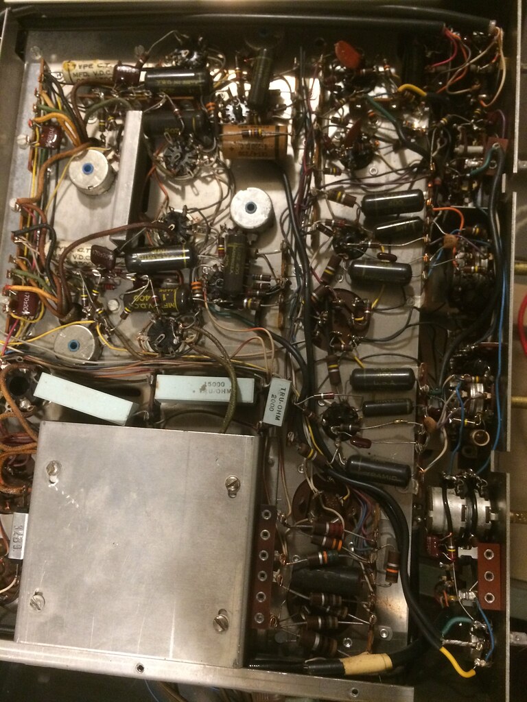
Looked pretty daunting with all those black beauties. I can't even get to all of them. Put in a giant parts order.
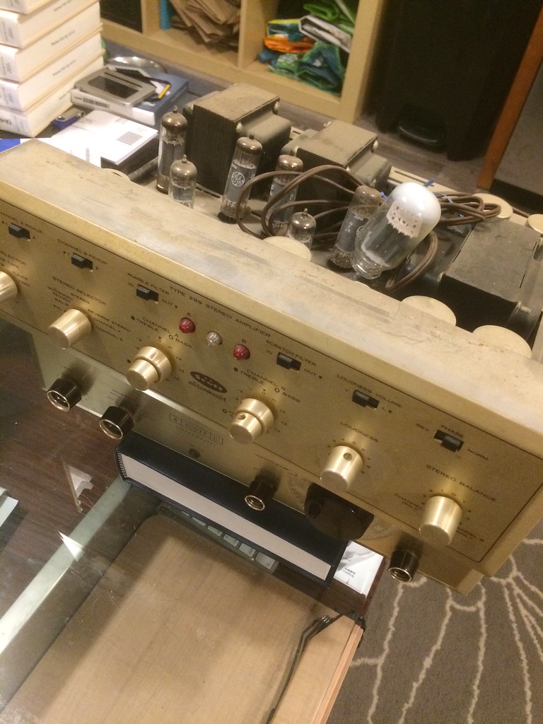
Progress so far:
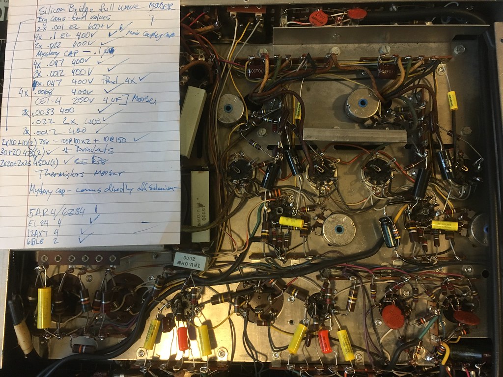
What's not visible is the silicon rectifier I threw at it. Read somewhere I need to add a 33 ohm resistor to it- where do I put that in the circuit?
Have another parts order coming with individual caps to rewire the multisection cans.
Still waiting on the 12AX7s, 6BL8s, and EL34s (to replace the 7198As). Have the 5AR4.
One of the dual concentric pots is frozen, and no amount of deoxit or d100 got it loose. Ordered a new 500k stacked pot, might have to turn some spacers for the original knobs to fit on it though.
My key takeaway so far is that this project would have taken a pro about 2.5 hours and cost about $600 in parts and labor. I'm currently over $400 SMH and been staring at it for weeks now.
I dusted it off and hit what I could with a brush before taking it apart. Went through and blasted crud out of all the pots (including the bias pots) and gave them all some faderlube.
Looked pretty daunting with all those black beauties. I can't even get to all of them. Put in a giant parts order.
Progress so far:
What's not visible is the silicon rectifier I threw at it. Read somewhere I need to add a 33 ohm resistor to it- where do I put that in the circuit?
Have another parts order coming with individual caps to rewire the multisection cans.
Still waiting on the 12AX7s, 6BL8s, and EL34s (to replace the 7198As). Have the 5AR4.
One of the dual concentric pots is frozen, and no amount of deoxit or d100 got it loose. Ordered a new 500k stacked pot, might have to turn some spacers for the original knobs to fit on it though.
My key takeaway so far is that this project would have taken a pro about 2.5 hours and cost about $600 in parts and labor. I'm currently over $400 SMH and been staring at it for weeks now.
Last edited:
I dare say that HH Scott never made a 'bad' amplifier in this era, and the 299 series is very well regarded. Glad to hear another one might be coming back to life, after some decades in the attic.
Better than decades in most any basement, for sure..
Thanks for the photo-narrative, keep us posted.
Better than decades in most any basement, for sure..
Thanks for the photo-narrative, keep us posted.
Still waiting on the 12AX7s, 6BL8s, and EL34s (to replace the 7198As).
Aside from being electrically incompatible, the EL34 employs an Octal base, while the 7189 employs a Noval (9 pin mini) base. Send 'em back or cancel the order, if possible. Like it or not, the Russian tube I previously mentioned is "the only game in town".

Buy tubes from a reputable dealer. My go to guy is Jim McShane, but other ethical merchants exist.
Hahaha, that's a typo. Nice spot though! They're EL84Ms.
Great, they're "exactly what the doctor ordered".
Delving deeper, you can check carbon composition resistors for noise and/or drift. Carbon film parts of appropriate resistance and wattage are excellent replacements. However, carbon composition parts should be retained in grid stopper positions. Leave wirewound resistors be, unless signs of physical deterioration are visible.
What's not visible is the silicon rectifier I threw at it. Read somewhere I need to add a 33 ohm resistor to it- where do I put that in the circuit?
I hope you installed a 4 diode bridge, in the correct orientation. A single diode will not do. The value of R106 needs to increase, to account for silicon's lower forward drop. Use a 5 W. rated part for the replacement and rest easy about increased I2R heating giving you grief.
I sure hope it's the right one- a Vishay KBL04-E4/51 4A/400V full wave bridge rectifier. I connected it exactly how the selenium rectifier was- black wire to positive, white to negative, transformer leads to "AC." The polarity is a little confusing- black seems to be "negative" these days. I traced the circuit on the diagram for R106, it was a carbon comp 10R with no rating on it- just twice as large as the other resistors. I pulled that 10R out of circuit and put a 33R 10W wirewound in its place.
As you can imagine, these caps were not easy to get to:


Here’s an after with some nice new Sprague orange drops:

Here’s the new R106- or at least that’s what I think it is. Probably overkill at 10W:

What I removed in the final round of small cap replacements:

As you can imagine, these caps were not easy to get to:
Here’s an after with some nice new Sprague orange drops:
Here’s the new R106- or at least that’s what I think it is. Probably overkill at 10W:
What I removed in the final round of small cap replacements:
Last edited:
Sorry to be so critical, but this is a classic example of poor & lazy workmanship.

Looks like the old caps were just cut away, and the new leads wrapped around the old joints and soldered on. This isn't at all workmanlike, and really needs to be re-done. The joints should be sucked fairly clean of old solder and the old leads unwound & removed. Only then should the new parts be installed, leads wrapped tight to the terminals.
When doing p2p wiring, the goal is to have a functional build even if no solder is applied. Now obviously, this isn't a good idea in practice, but it's what you want in the back of your head when you are building a circuit p2p. Try to build it such that it would work, without solder.. and then apply the solder carefully.
Last edited:
Thanks for pointing out the bad joint, I'll fix that post haste.
The second I start messing around with removing all of the old solder I'm going to reconnect something in the wrong place and that will be the end of the project.
I'm not an engineer- I barely know what the symbols on a schematic mean. My only goals here are to get it running and not kill myself or burn down the house in the process. After this, I'm back to PCBs and casework for my DIY projects.
I'm going to happy if it doesn't catch on fire when I plug it in to my buddy's variac. I don't plan on doing any of this ever again... if it works, awesome, I'll button it up and listen to it until it dies or I do. If it doesn't work at all or dies on me, I've got a local resource who I'm sure will happily redo every connection for $30/hr and I will happily pay it if/when that happens.
Apparently there were three previous capacitors in that spot- why would that particular cap need to be replaced multiple times when there were still original caps almost everywhere else in the amp?
Perhaps a part whose WVDC is higher than originally called for is needed. H.H. Scott was good, but ALL humans err.
I'm not an engineer- I barely know what the symbols on a schematic mean. My only goals here are to get it running and not kill myself or burn down the house in the process. After this, I'm back to PCBs and casework for my DIY projects.
You have been bitten by the P2P bug. "Resistance is futile!"
You'll be be back for more. The caution you exhibit will serve you very well.The pics show what look like 715P series Orange Drops. Those have steel leads, which is not the end of the Earth, but steel leads are undesirable. Use 716P series parts, with copper leads, from here forward.
Double check your bridge rectifier installation. The positive leg gets grounded. Remember you are dealing with a C- (bias) rail that happens to also provide DC heater power for some small signal tubes.
BTW, after getting the unit going, if the sound is a too "bright/forward" to your ears, you can swap out some the new film caps. for Soviet surplus K40 paper in oil (PIO) parts.
August 2018 Update:
I ended up sending the amp out to AEA for a deep clean and some upgrades I wasn't comfortable with. That was June of 2017. I still don't have it back and Ken Leonard hasn't responded to an email since November and hasn't picked up the phone since April.
I've been calling and emailing every few weeks and I'm starting to wonder if I'm ever going to see it again.
Still haven't heard it since it was in my grandfather's study in 2008. A sad end to a cool old piece of kit.
I had big plans for it- I built some of Troels' speakers to go with it, and they've been up and running with a spare tube hybrid for nearly a year now. I went with the discovery 15 and really love them. Saved some purple heart from the build to work into the new case for the 299, but it's just been gathering dust.
Look at the 299A schematic.
. Install the series SS diode tweak and the highly affordable Sovtek 5AR4 will be fine as the B+ rectifier. FWIW, my preference is the UF4007, instead of the 1N4007.
I implemented this scheme in a vintage amp to use with currently made 5ar4 . Could you explain how the 2 diodes protect the inferior 5ar4 sold nowadays.
The Sovtek 5AR4 is fine, with 1 key exception. The variant gets into trouble at the top of the documented voltage range. The SS diodes provide some critical extra PIV headroom. No "fireworks" with the "sand" in series with the plates.
BTW, New Sensor is offering some ("surprise" more costly) 5AR4s that are supposedly flaw free.
BTW, New Sensor is offering some ("surprise" more costly) 5AR4s that are supposedly flaw free.
- Status
- This old topic is closed. If you want to reopen this topic, contact a moderator using the "Report Post" button.
- Home
- Amplifiers
- Tubes / Valves
- Scott 299A Rebuild