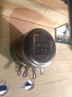
I'm making a breadboard to start the Fi Primer 300b and am wondering how to wire the hum pot. At the local electronics supplier I picked up a dual 100 ohm, 2 watt Allen Bradley Type J linear taper pot (picture attached). Everything I've found online assumes you already know how to wire it.
If I place a meter on the two outer tabs, it reads 100 ohm no matter where the knob is turned to, but if I measure from either end to the center the value changes as I turn the knob, and each side is more or less the difference to 100 of the other side.
So, which tabs go to the filament pins and which one is for cathode resistor/cap to ground?
My guess is that the center lead would get the cap/resistor, since its resistance will always be more or less constant as the two ends trade portions of the 100 ohm load. Is that correct?
Attachments
....
My guess is that the center lead would get the cap/resistor ....
Yes. It's a virtual center tap.
Win W5JAG
Thanks for clarifying, Win. I've got a breadboard up and running now, and the hum pots work well.
The amp sounds good but the target voltages are off. I used all of the values in the Fi Primer schematic except for three things:
* PS filter choke is 6H instead of 5H (because it's what I had lying around)
* 300B cathode resistor is 1.5k instead of 880 ohm (to keep the plate current down to 50mA)
* OPT primary impedance is 5K instead of 3-3.5K
The voltages measured as follows:
* B+ 478V (was aiming for 438)
* 300B Vp 467V (was aiming for 425)
* 300B Vk 86V (was aiming for 75)
* 6SN7 Vp1 58V (was aiming for 71)
* 6SN7 Vp2 155V (was aiming for 210)
Unless you have other advice, I'm thinking I need a dropping resistor in the PS and a lower value one heading to the two 6SN7 plates. Just have to figure out the values.
Also, I absolutely could not get a 300B plate current measurement. My multimeter simply would not show anything when I measured across the OPT primary or the cathode resistor. Is it my technique? Maybe I should buy a real multimeter and ditch the $5 Harbor Freight ones?
Well I figured out part of it. Since this is a stereo build and the schematic shows a single channel, there will be more current flowing through the shared PS parts and therefore more voltage drop through those resistors. Also there is more load on the PT and therefore more voltage draw --> higher voltages. I added the second channel to my LTSpice model and it's pretty close too what I'm measuring on the breadboard.
Also I found a multimeter with a working current section and got 58mA across the OPT primary, which matches the updated model.
Also I found a multimeter with a working current section and got 58mA across the OPT primary, which matches the updated model.
Last edited:
I've been listening to this amp at various operating points for more than a week now and really enjoying it.
Though I was aiming to start with the WE suggested spec for the 300B of 350Vak/50mA into a 5K load, I haven't quite been able to hit that because I need to get more resistors for the PS and haven't had time to go to the store.
So far I've tried it with the 300Bs at 382Vak/56mA, 372Vak/54mA, and 362Vak/52mA. It sounds best at 382 (more "air") and 362 (more control and balance).
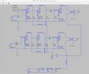
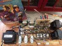
Attached is a schematic showing all the component values and op points of what I'm currently listening to (382Vak/56mA) as well as a pic of the live beast.
I'd like to try the 400Vak/60mA op point but will need higher voltage caps for the PS, as the ones I currently have are 500V and it will likely draw more than that in that section.
Though I was aiming to start with the WE suggested spec for the 300B of 350Vak/50mA into a 5K load, I haven't quite been able to hit that because I need to get more resistors for the PS and haven't had time to go to the store.
So far I've tried it with the 300Bs at 382Vak/56mA, 372Vak/54mA, and 362Vak/52mA. It sounds best at 382 (more "air") and 362 (more control and balance).
Attached is a schematic showing all the component values and op points of what I'm currently listening to (382Vak/56mA) as well as a pic of the live beast.
I'd like to try the 400Vak/60mA op point but will need higher voltage caps for the PS, as the ones I currently have are 500V and it will likely draw more than that in that section.
Attachments
Last edited:
Today I tried taking the hum pots out of the circuit and attaching the center tap on the 5V filament transformers to the 300B cathode resistors and bypass caps. Hum is equally as low (listening, not testing) as when the hum pots were dialed in but the sound is a little less vibrant.
The change seems to have brought the operating points down just slightly. Before they were:
* 300B -- 382Vak/56mA
* 6SN7 -- Vp1 74.5V, Vp2 219V
Now the 300Bs are a little less high but the 6SN7s are just about on target for the original schematic.
* 300B -- 380Vak/53mA
* 6SN7 -- Vp1 70V, Vp2 209V
Perhaps the slight change in op points is enough to change the sound, but it didn't seem as vibrant and airy to me today. Bass also seemed a little boomy.
I prefer the higher op points and I'm guessing it'll sound better when I put the hum pots back in.
First of all, I would like to thank the OP for starting the thread and to all who have contributed. Learned a lot by going through the posts.
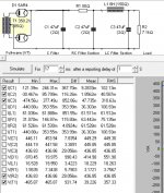
I am simulating a PSU similar to the one that the OP has chosen using a 700 VCT 120mA transformer for a mono-block 300B configuration. I see lot of 300B stereo designs use 200mA transformers, so I am assuming that 120mA at high enough voltages should work for mono-blocks. The sim also seems to agree.
I am sharing an image of the simulation below. The sim result shows 436V B+. Does this look ok, or I am overlooking some key things?
Attachments
That sim looks OK to me. I've recently been modeling circuits with a current source as the load, rather than a resistor. You add up all the current draw from the tubes in the circuit and make that the load. So, say you're going to run the 300B at 60mA, and you're using the two halves of a 6SN7 in a voltage amp/cathode follower configuration at 4mA and 8mA (I'm just making this up -- not pertaining to any particular circuits). Your current source load would be 60 + 4 + 8 = 72mA.
As far as whether 120mA is enough for your circuit, it depends on the total current draw of the input and output tubes. What circuit are you planning to build?
As far as whether 120mA is enough for your circuit, it depends on the total current draw of the input and output tubes. What circuit are you planning to build?
What circuit are you planning to build?
Thinking of experimenting with the JE 300B and/or the circuit you shared in your first post.
- Status
- This old topic is closed. If you want to reopen this topic, contact a moderator using the "Report Post" button.
- Home
- Amplifiers
- Tubes / Valves
- Modeling Fi Primer 300B with LTSpice